Factory Shop Manual For Komatsu Hydraulic Excavator. Manual Contains Illustrations, Instructions, Diagrams For Step By Step Remove And Install, Assembly And Disassembly, Service, Inspection, Repair, Troubleshooting, Tune-Ups.
Format: PDF
Language: English
Pages: 440
Number: WEBMPW9500
Searchable: Yes
Wiring Diagrams: Yes
Hydraulic Diagrams: Yes
Model
Komatsu Hydraulic Excavator
PW95-1
SN 0000007 And Up
Contents
FOREWORD
-STRUCTURE AND FUNCTION
PTO
Power Train
Transmission
Front Axle – Differential
Rear Axle – Differential
Planetary
Axles
Parking Brake And Cylinder
Steering System
Steering Unit
Swing Circle
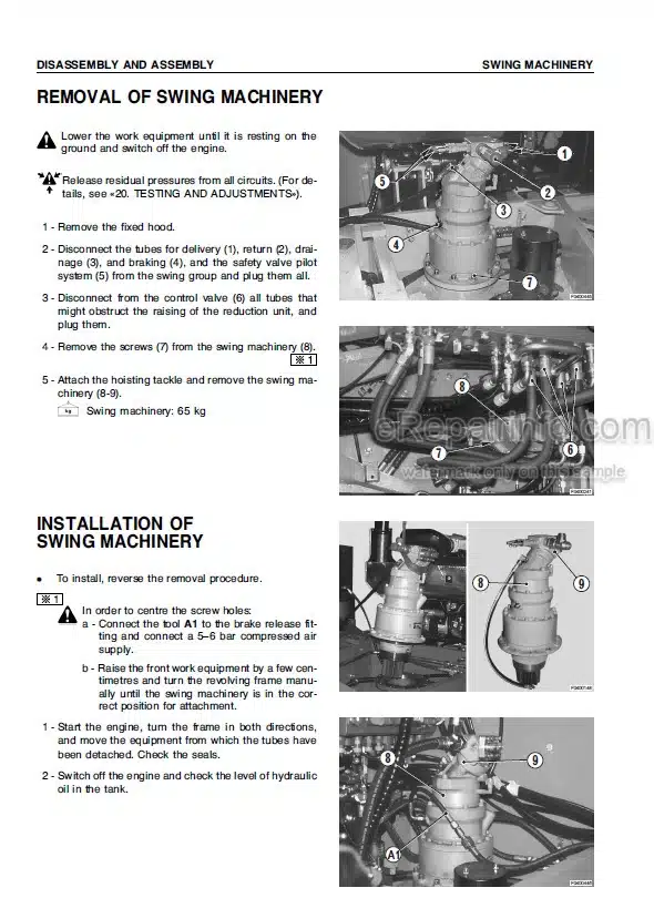
Swing Machinery
Check Valve And Oil Cooler Safety By-Pass
Hydraulic Circuit Diagram
Main Hydraulic Pump
Pump Drive
Summation Horsepower Control
3 Circuit Control Valve
Mode-System
Auxiliary Pump
Priority Valve
Control Valve (Valve)
Control Valve (Ports)
Swing Motor
Swing Motor Relief Valve
Center Swivel Joint
Travel Motor
Displacement Automatic Control High Pressure Related
Travel Motor Brake Valves
Servocontrol Feed Unit
RH PPC Valve
LH PPC Valve
Accumulators
Swing Motor Braking Circuit Selector Valve
Travel PPC Valve
2nd Boom PPC Valve
Boom Swing PPC Valve
Outrigger And Blade PPC Valve
Outrigger And Blade Safety Valve
Brake Pump
Axle Locking Valve
Solenoid Valves
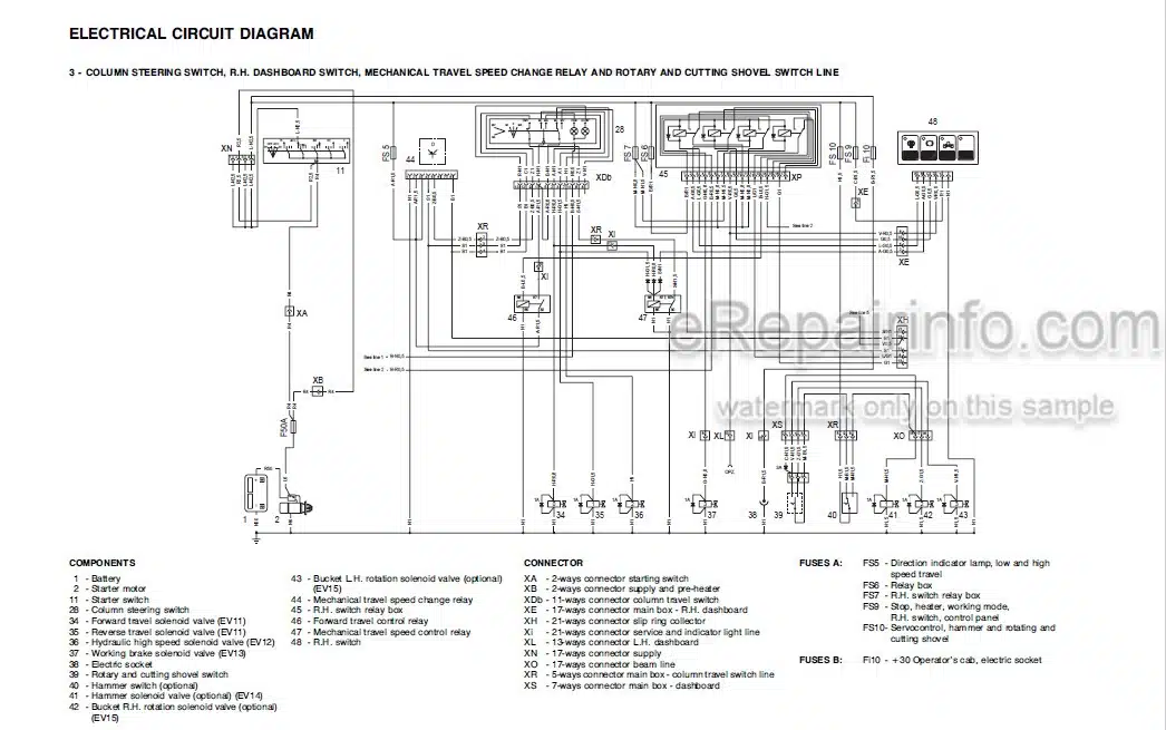
Electrical Circuit Diagrams
-TESTING AND ADJUSTING
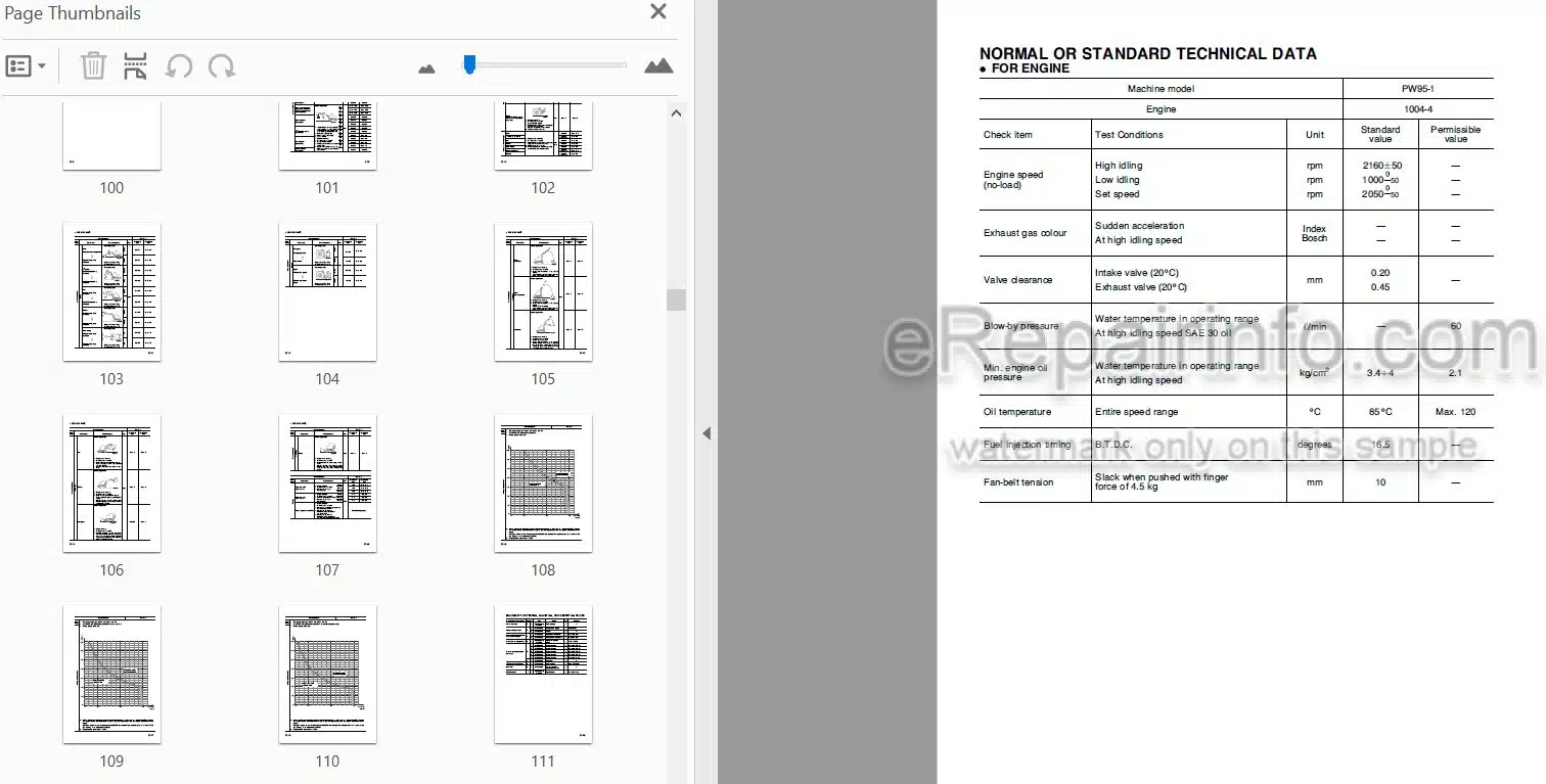
Normal Or Standard Technical Data
Equipment For Testing, Adjusting And Identifying Faults
Measuring The Engine Speed
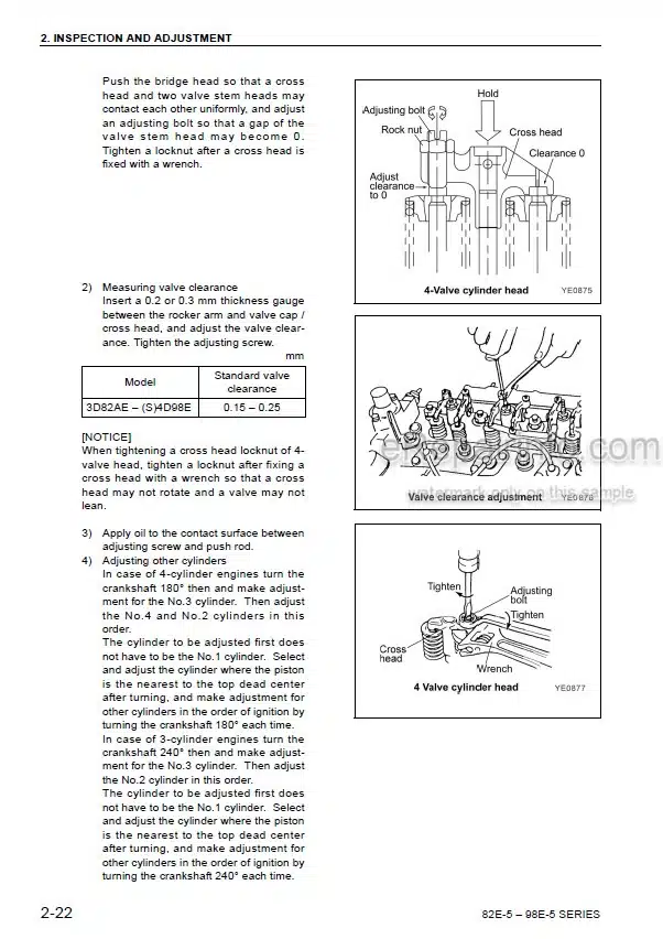
Valve Clearance Adjustment
Measurement Of Compression Pressure
Checking And Tightening The Fan-Belt
Adjusting The Stroke Of The Accelerator Lever
Adjusting PPC Valves Clearance
Adjusting The Safety Microswitch
Centering The Stroke Of The Blade And The Outriggers Control Lever
Measuring The Swing Circle Axial Clearance
Bleeding Air From Pumps (P1 And P2)
Bleeding Air From The PPC Valves Circuit
Bleeding Air From The Load Sensing Circuit
Bleeding Air From The Cylinders
Releasing Residual Pressure From The Circuits
Releasing Residual Pressure From The Brake Line Accumulators
Checking And Regulating Pressure In The Hydraulic Circuits
Checking The Intervention Point Of The Summation
Horsepower Control
Checking The Initial Horsepower Control Point For The 3-Circuit Control Valve
Checking And Adjusting Pressures In The Servocontrol Supply Units
Adjusting The Main Safety Valve Of Pump P4
Measuring Pump Delivery
Checking That The Priority Valve Is Functioning Correctly
Checking And Regulating The Pressure Of The Steering System
Checking Leakages In The Steering Cylinders
Checking The Braking System
Checking Wear In The Brake Disks
Bleeding Air From The Brake Lines
Adjusting The Parking Brake
Checking The Hydraulic Travel System
Checking And Adjusting The Safety Valves Of The Travel Motor
Checking And Adjusting The Automatic Displacement Control System Of The Travel Motor
Checking For Leakages In The Travel Motor
Checking And Adjusting The Speed Of The Travel Propeller Shaft
Adjustment Of The Speed Surveyor
Adjusting Boom And Arm Safety Valves
Adjusting 2nd Boom Safety Valves
Measuring The Initial Intervention Point Of The Overload Sensor
Adjusting The Valve That Controls The Closing Speed Of The 2Nd Boom
Measurement Of Internal Oil Leakages In The Swing Motor
Checking For Leakages Inside The Swivel Joint
Analysis Of The Causes Of Hydraulic Drifts
-DISASSEMBLY AND ASSEMBLY
How To Read The Manual
Precautions To Be Taken When Working
Special Tools
Starter Motor
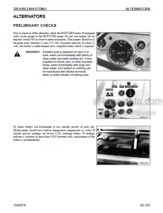
Alternator
Nozzle Holder
Air Filter Group
Muffler
Engine Hood
Fixed Hood
Seat
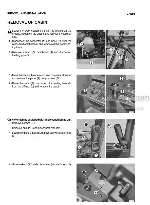
Cabin
Counterweight
Radiator
Hydraulic Oil Cooler
Heating Fan
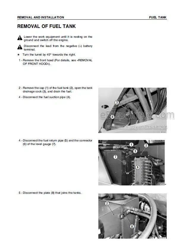
Fuel Tank
Hydraulic Oil Tank
Engine-Pump Group
Pump Group
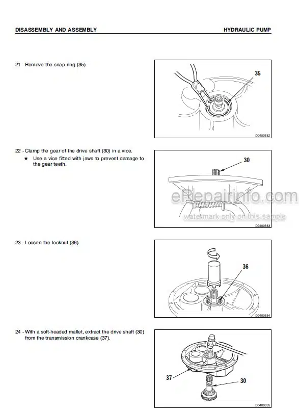
Hydraulic Pump
Gear-Pump
Engine-Pump Coupling Joint
Swivel Joint
Swing Motor
Swing Machinery
Revolving Frame
Swing Circle
Transmission – Reverser, Direction Indicator And Headlight Dipper Beam Control Group
RH PPC Valve (Boom – Bucket)
LH PPC Valve (Arm-Swing)
Blade PPC Valve
Removal Of PPC Valve (For Travel, Boom Swing, 2-Piece Boom)
Brake Pump
Servocontrol Supply Group
Control Valve
Travel Motor
Transmission
Steering Unit
Priority Valve
Axle-Locking Valve Group
Check Valve
Axle-Locking Cylinder
Complete Front Axle
Complete Rear Axle
Axles
Boom Cylinder
Boom Cylinder (For 2-Piece Boom)
2-Piece Boom Cylinder
Arm Cylinder
Bucket Cylinder
Boom Swing Cylinder
Cylinders For Outriggers/Blade
Work Equipment Cylinders
Overload Sensor
Work Equipment (For The Boom)
Work Equipment (2-Piece Boom Version)
Bucket
Arm
2-Piece Boom
Boom
Boom (2-Piece Boom Version)
Swing Bracket
Blade And Outrigger
Blade And Outrigger Arms
-MAINTENANCE STANDARD
PTO
Transmission
Front And Rear Axles Differential
Brake Disks
Planetary – Articulation
Axles
Steering Cylinder
Parking Brake And Cylinder
Swing Circle
Swing Machinery
Check Valve And Oil Cooler Safety By-Pass
Pump Drive
Summation Horsepower Control – Mode-System
Auxiliary Pump
Control Valve
Swing Motor Relief Valve
Travel Motor
Travel Motor Brake Valves
Servocontrol Feed Unit
Axle Locking Valve
LH And RH PPC Valves
Travel PPC Valve
2nd Boom And Boom Swing PPC Valve
Outrigger And Blade PPC Valves
Outrigger And Blade Safety Valves
Axle Locking Cylinder
Cylinders
Work Equipment (1 – Piece Boom)
Work Equipment (2 – Piece Boom)
What you get
You will receive PDF file with high-quality manual on your email immediately after the payment.
Reviews
There are no reviews yet