


Factory Shop Manual For Komatsu Wheel Excavator. Manual Contains Illustrations, Instructions, Diagrams For Step By Step Remove And Install, Assembly And Disassembly, Service, Inspection, Repair, Troubleshooting, Tune-Ups.
Format: PDF
Language: English
Pages: 1180
Number: VEBM400101 (may 2008)
Bookmarks: Yes
Searchable: Yes
Wiring Diagrams: Yes
Hydraulic Diagrams: Yes
Model
Komatsu Wheel Excavator
PW180-7E0
SN H55051 And Up
Contents
FOREWORD
-GENERAL
Specification Dimension Drawings
Working Ranges
Specifications
Weight Table
Fuel, Coolant And Lubricants
-STRUCTURE AND FUNCTION, MAINTENANCE STANDARD
Engine Related Parts
Radiator – Oil Cooler – Charge Air Cooler
Powertrain
Swing Circle
Swing Machinery And Motor
Swing Motor
Undercarriage
Transmission
Quick Coupler Control Valve
ATT EPC Valve Assembly
Travel Motor
Clutch Control Circuit
Axle
Suspension Lock Cylinder
Braking System
Brake/Steer Pump
Priority Valve
Power Brake Valve
Accumulator For Brake Valve
Steering System
Steering Column
Orbitrol Valve
Hydraulic Equipment Layout Drawings
Hydraulic Circuit Diagram
Hydraulic Tank
Hydraulic Pump
Pilot Pressure Control (PPC) System
Control Valve
CLSS
Centre Swivel Joint
Travel PPC Pedal
Work Equipment – Swing PPC Valve
Solenoid Valve Block
Boom Safety Valve
Hydraulic Cylinder
Outrigger Cylinder
Dozer Cylinder
Work Equipment
Air Conditioner
Electrical Wiring Diagram
Electrical System
Electronic Control System
Machine Monitor System
Overload Warning Device
1St Attachment Circuit Hydraulic Performance (Main Valve Bypassed)
Travel System
Steering System
Service Brake And Suspension System
Komtrax Terminal System
-TESTING AND ADJUSTING
Standard Value Table For Engine Related Parts
Standard Value Table For Chassis Related Parts
Flow Control Characteristic Of PC Valve (STD)
Testing And Adjusting
Troubleshooting
Troubleshooting When Failure Code Is Indicated
Troubleshooting Of Electrical System (E-Mode)
Troubleshooting Of Electrical System (Error Checking Of Items Without Monitor Codes)
Troubleshooting Of Hydraulic And Mechanical System (H-Mode)
Measuring Engine Speed
Measuring Intake Air Pressure (Boost Pressure)
Measurement Of Exhaust Gas Color
Adjusting Valve Clearance
Measuring Compression Pressure
Measuring Blow-By Pressure
Measuring Engine Oil Pressure
Handling Fuel System Parts
Releasing Residual Pressure From Fuel System
Measuring Fuel Pressure
Measuring Fuel Return Rate And Leakage
Bleeding Air From Fuel Circuit
Checking And Adjusting Air Conditioner Compressor Belt Tension
Measurement Of Clearance In Swing Circle Bearings
Inspection And Adjustment Of Hydraulic Oil Pressure In Hydraulic Circuit For Work Equipment, Swing And Travel
Inspection And Adjustment Of Control Circuit Oil Pressure]
Inspection And Adjustment Of Pump PC (Valve Inlet) Control Oil Pressure
Inspection And Adjustment Of Pump Is Valve Control Oil Pressure
Measurement Of Solenoid Valve Output Pressure
Measurement Of PPC Valve Output Pressure
Adjustment Of Work Equipment And Swing PPC Valve
Measuring And Adjusting Quick Coupler Control Valve Output Pressure
Troubleshooting
Points To Remember When Troubleshooting
Sequence Of Events In Troubleshooting
Points To Remember When Carrying Out Maintenance
Checks Before Troubleshooting
Classification And Steps For Troubleshooting
Connector Location Chart And Electrical Circuit Diagram By System
Connection Table For Connector Pin Numbers
Troubleshooting When Failure Code Is Indicated
Troubleshooting Of Electrical System (E-Mode)
Troubleshooting Of Electrical System (Error Checking Of Items Without Monitor Codes)
Troubleshooting Of Hydraulic And Mechanical System (H-Mode)
-DISASSEMBLY AND ASSEMBLY
Coating Materials List
Special Tools List
Precautions When Performing Operation
Removal And Installation Of Fuel Supply Pump Assembly
Removal And Installation Of Fuel Injector Assembly
Removal And Installation Of Engine Front Seal
Removal And Installation Of Engine Rear Seal
Removal And Installation Of Cylinder Head Assembly
Removal And Installation Of Combination Cooler Assembly
Removal And Installation Of Fuel Cooler Assembly
Removal And Installation Of Engine And Hydraulic Pump Assemblies
Removal And Installation Of Travel Motor Assembly
Disassembly And Assembly Of Travel Motor Assembly
Removal And Installation Of Swing Motor And Swing Machinery
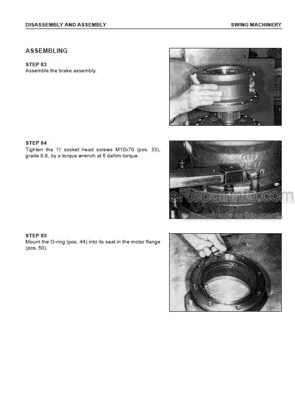
Disassembly And Assembly Of Swing Machinery
Disassembly And Assembly Of Swing Motor Assembly
Removal And Installation Of Front Axle Assembly
Disassembly And Assembly Of Front Axle
Removal And Installation Of Rear Axle And Transmission
Disassembly And Assembly Of Rear Axle Assembly
Removal Of Epicyclic Reduction Gear And Brake
Installation Of Epicylic Reduction Gear And Brake
Disassembly Of Beam Trumpet And Differential Unit
Installation Of Beam Trumpet And Differential Unit
Disassembly Of Pinion Group
Installation Of Pinion Group
Disassembly And Assembly Of Transmission
Removal And Installation Of Propshaft Assembly
Removal And Installation Of Wheel Assembly
Removal And Installation Of Suspension Lock Cylinder Assembly
Disassembly And Assembly Of Suspension Lock Cylinder
Removal And Installation Of Outrigger Assembly
Disassembly And Assembly Of Outriggers
Removal And Installation Of Dozer Blade Assembly
Disassembly And Assembly Of Dozer Blade
Removal And Installation Of Swing Circle Assembly
Removal And Installation Of Revolving Frame Assembly
Removal And Installation Of Centre Swivel Joint
Disassembly And Assembly Of Centre Swivel Joint Assembly
Removal And Installation Of Fuel Tank Assembly
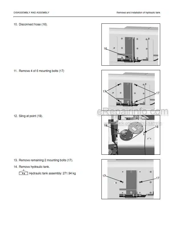
Removal And Installation Of Hydraulic Tank Assembly
Removal And Installation Of Control Valve Assembly
Removal And Installation Of LS Separation Valve Assembly
Removal And Installation Of Pressure Compensation Valve Assembly
Removal And Installation Of Main Relief Valve Assembly
Removal And Installation Of LS Control EPC Valve
Removal And Installation Of EPC Solenoid Valve Assembly
Removal And Installation Of PPC Solenoid Valve Block Assembly
Removal And Installation Of Oil Seal In Hydraulic Pump Input Shaft
Disassembly And Assembly Of Work Equipment PPC Valve
Disassembly And Assembly Of Hydraulic Cylinder
Removal And Installation Of Monoboom Work Equipment
Removal And Installation Of 2 Piece Boom Work Equipment
Removal And Installation Of Air Conditioner Unit
Removal And Installation Of Counterweight
Removal And Installation Of Operator Cab Assembly
Removal And Installation Of Monitor Assembly
Removal And Installation Of Pump Controller Assembly
Removal And Installation Of Komtrax Terminal
-OTHER
Hydraulic Circuit Diagram
Electrical Circuit Diagram
What you get
You will receive PDF file with high-quality manual on your email immediately after the payment.


Reviews
There are no reviews yet