Factory Service Manual For Bomag Compact Milling Machine. Manual Contains Illustrations, Instructions, Diagrams For Step By Step Remove And Install, Assembly And Disassembly, Service, Inspection, Repair, Troubleshooting, Tune-Ups.
Format: PDF
Language: ENG
Pages: 1178
Number: 00891685 (october 2012)
Bookmarks: Yes
Searchable: Yes
Wiring Diagrams: Yes
Hydraulic Diagrams: Yes
Model
Bomag Compact Milling Machine
BM 500/15
BM 600/15
S/N 101 882 00 1001 ….
S/N 101 882 01 1001 ….
S/N 101 882 10 1001 ….
S/N 101 882 11 1001 ….
Contents
-GENERAL
Introduction
Safety Regulations
General Repair Instructions
Tightening Torques
-TECHNICAL DATA
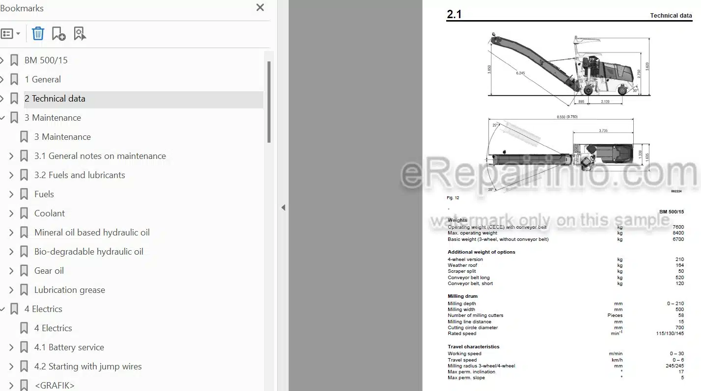
Technical Data
-MAINTENANCE
General Notes On Maintenance
Fuels And Lubricants
Table Of Fuels And Lubricants
Running-In Instructions
Maintenance Table
-ELECTRICS
Battery Service
Starting With Jump Wires
Main Battery Switch
Main Fuse
Fuses
Component Overview
Overview Of Wiring Looms
Control Elements
Overview
Multi-Function Display
Data Collector
Functional Block Diagram Overview Of Functions, Complete
Functional Block Diagram Components Connected To Can1 And Can2
Functional Block Diagram Can1 And Can2 With Control Elements
Block Diagram Of Travel Circuit
Functional Block Diagram For Conveyor Belt Drive
Functional Block Diagram Milling Drive
Functional Block Diagram Functions Without Control
Functional Block Diagram Height Adjustment With Levelling
Functional Block Diagram Height Adjustment Without Levelling
Functional Block Diagram Switches In Display And On Travel Lever
Functional Block Diagram Telematic
Functional Block Diagram Monitoring Functions
Functional Block Diagram Water Sprinkling System
Functional Block Diagram Emergency Stop Function
Air Filter Vacuum Switch
Float Switch, Coolant Tank
Water Tank Filling Level.
Charge Control Light, Operating Hour Meter
Functional Conditions Left Side Plate
Functional Conditions Right Side Plate
Functional Conditions For Hold-Down
Functional Conditions For Scraper
Functional Conditions Support Wheel Rear Left
Functional Condition Support Wheel Rear Right
Operating Conditions For Conveyor Belt
Conditions For Milling
Functional Conditions For Brake
Electronic Control Units
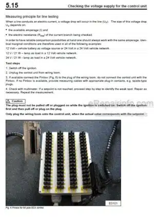
Checking The Voltage Supply For The Control Unit
Diagnostics Concept
-CODES — GENERAL INFORMATION
Error Codes – General Information
Query Codes – General Information
Input Codes – General Information
-ERROR CODES
Error Code Lists
-QUERY CODES
Query Code Lists
-INPUT CODES
Input Codes – Display Function And Operation
Input Codes – Restoring Factory Settings
Input Codes Calibration Of Surge Currents For Height Adjustment
Input Codes – Showing Logged Errors
Input Codes – Showing Logged Errors With Operating Hours
Input Codes – Deleting The Error Log
-REPLACEMENT OF COMPONENTS
How To Proceed When Replacing Components
-ENGINE
Diesel Engine
Engine Description TCD 2012
Lubrication Oil Circuit TCD 2012 / 2013
Coolant Circuit TCD 2012 / 2013
Fuel System TCD 2012 / 2013
Deutz Common Rail (DCR) Injection System For TCD 2012 / 2013
Exhaust Gas Recirculation TCD 2012 / 2013
Checking The Engine Oil Level
Change Engine Oil And Oil Filter Cartridge
Checking, Cleaning The Water Separator
Replacing The Fuel Pre-Filter Cartridge, Bleed The Fuel System
Replace The Fuel Filter Cartridges
Air Filter Maintenance
Checking The Coolant Level
Check The Anti-Freeze Agent Concentration
Changing The Coolant
Clean The Cooling Fins On Engine And Hydraulic Oil Cooler
Checking / Replacing The Ribbed V-Belt
Check The Engine Mounts
Adjust The Valve Clearance
Adjusting The Control Piston Play
Engine Problems
Special Tools, Deutz Engine (TCD 2012 2V)
-ENGINE ELECTRICS
Emr3 System Components
Pin Assignment Of Engine Control EDC16 / EMR3
Rotary Speed Sensor For Camshaft
Rotary Speed Sensor For Crankshaft
Rail Pressure Sensor
Fuel Pressure Sensor
Fuel Control Unit
Injector
Oil Pressure Sensor
Sensor For Charge Air Temperature And Charge Air Pressure
EMR Coolant Temperature Sensor
Glow Plugs
Sensor, Water In Fuel
Diagnose With Serdia
EMR3 List Of Fault Codes
Diagnose With Can-Bus
Diagnostics Interface
-MILLING DRIVE, DESCRIPTION
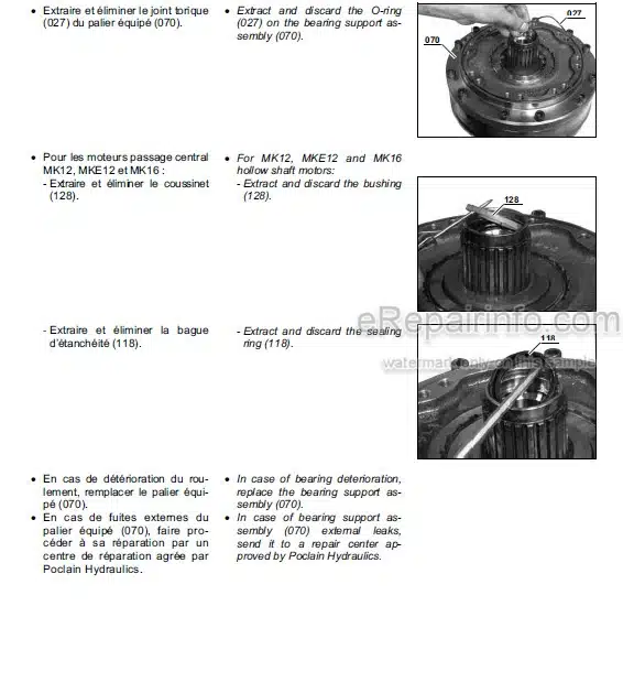
Milling Drive
-MILLING DRIVE, REPAIR
Overview Clutch Repair
Repair Overview V-Belt Unit
Gearbox Repair Overview
Remove The Clutch
Install The Clutch
Checking, Tightening, Replacing The V-Belt For The Milling Drum Drive
Remove The Gearbox
Install The Gearbox
Milling Drum Spur Wheel Gear, Oil Change
Checking Milling Cutters And Scraper Bar, Replacing If Required
Checking The Friction Liner Wear
-MILLING DRUM, DESCRIPTION
Milling Drum
-MILLING DRUM, REPAIR
Repair Overview Milling Drum
Replacing Tool Holders
Replacing The Milling Drum
-MILLING DRUM HOUSING, DESCRIPTION
Milling Housing
-MILLING DRUM HOUSING, REPAIR
Repair Overview Hold-Down
Repair Overview Right Hand Side Plate
Repair Overview Left Hand Side Plate
Repair Overview Scraper
Repair Overview Scraper, Split
Remove The Hold-Down
Install The Hold-Down
Remove The Left Side Plate
Install The Left Side Plate
Remove The Right Side Plate
Install The Right Side Plate
Remove The Scraper
Install The Scraper
-CONVEYOR BELT, DESCRIPTION
Conveyor Belt
-CONVEYOR BELT, LONG – REPAIR
Repair Overview Conveyor Belt
Check, Tighten The Conveyor Belts
Lubricating The Conveyor Belt
Checking Safety Rope And Chain
-CONVEYOR BELT, SHORT – REPAIR
Repair Overview Conveyor Belt, Short
-TRAVEL DRIVE, DESCRIPTION
Travel System
-TRAVEL DRIVE, REPAIR
Repair Overview Support Wheel Rear Left
Repair Overview Support Wheel Rear Right
Repair Overview Front Axle 3-Wheeler
Repair Overview Front Axle 4-Wheeler
Repair Overview Steering
Remove The Rear Left Support Wheel
Install The Rear Left Support Wheel
Remove The Rear Right Support Wheel
Install The Rear Right Support Wheel
Lubricating The Steering (3-Wheeler)
Lubricating The Steering (4-Wheeler)
-HYDRAULICS – GENERAL
Hydraulic Circuit
Hydraulics – Component Overview
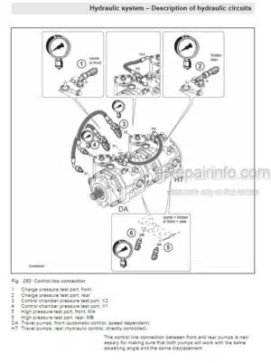
Description Of Travel Pump
Troubleshooting Axial Piston Pumps
View Of The Machine
Description Of Working Pump
View Of The Machine
Description Of Tandem Pump
View Of The Machine
Description Of Poclain Travel Motor
View Of The Machine
Description Of Travel Motor Bosch Rexroth
View Of The Machine
Checking The Hydraulic Oil Level
Checking Hydraulic Hoses And Electric Cables
Changing The Hydraulic Oil
Change The Hydraulic Oil Filter
-HYDRAULICS – TRAVEL CIRCUIT
Description Of Driving
Description Of Crawler System
-HYDRAULICS – MILLING OPERATION
Description Of Clutch
View Of The Machine
Milling Box Hydraulics
View Of The Machine
-HYDRAULICS – FURTHER FUNCTIONS
Conveyor Belt Hydraulics
Protective Roof Hydraulics
-TESTS AND ADJUSTMENTS
Special Tools, Tests And Adjustments
Checking And Adjusting The Levelling
Checking/Adjusting The Roof Adjustment
Checking And Adjusting The Clutch Operating Pressure
Checking/Adjusting The Brake Releasing Pressure
Checking And Adjusting The Steering Pressure
Checking And Adjusting Working Hydraulics “MP”
Checking And Adjusting Working Hydraulics “MP1”
Checking/Adjusting The Scraper Pressure
Conveyor Belt: Checking And Adjusting The Pressure
Hydraulic Breaker: Checking And Adjusting The Pressure
Checking / Adjusting The Maximum Pressure Of The Travel Pump
-SUPPLIERS DOCUMENTATION
Travel Pump
Travel Motor
Steering Valve
Travel Motor
Conveyor Belt Motor
-CIRCUIT DIAGRAMS
Hydraulic Diagram
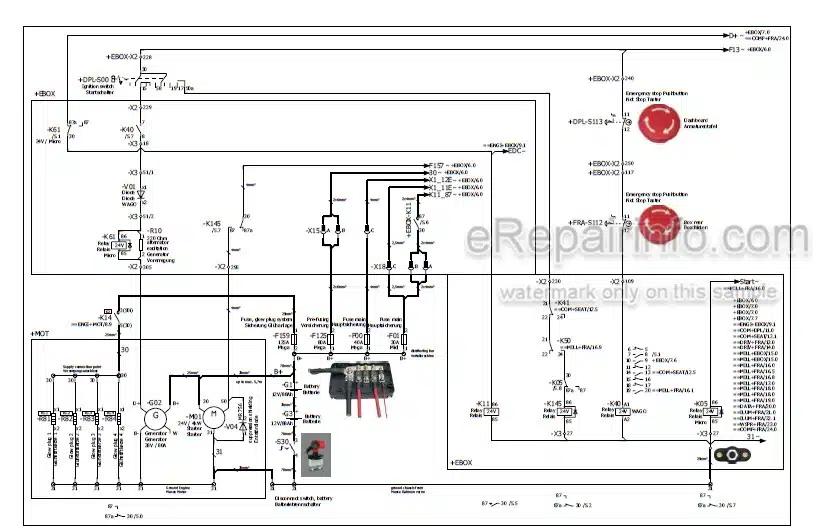
Wiring Diagram
What you get
You will receive PDF file with high-quality manual on your email immediately after the payment.



Reviews
There are no reviews yet