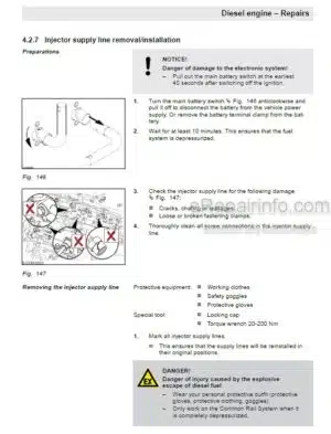
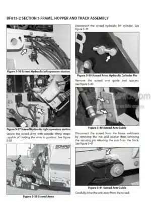
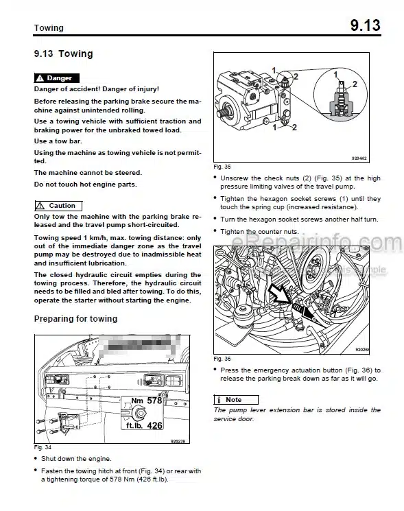
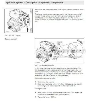
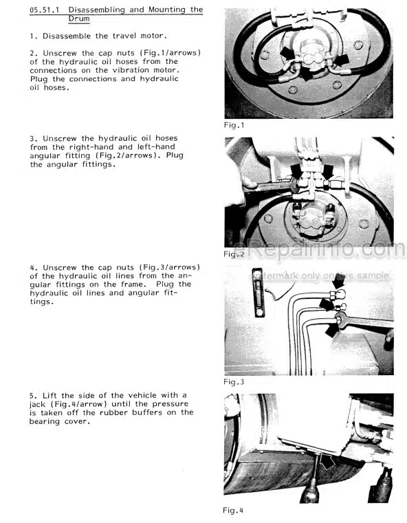
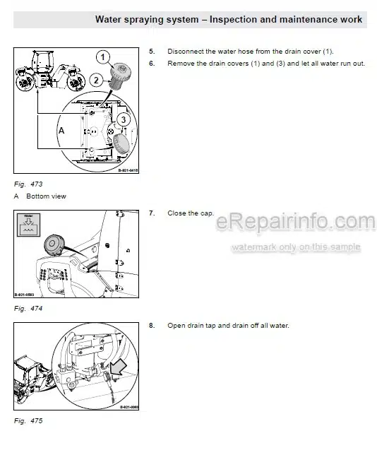
Factory Service Manual For Bomag Cold Milling Machine. Manual Contains Illustrations, Instructions, Diagrams For Step By Step Remove And Install, Assembly And Disassembly, Service, Inspection, Repair, Troubleshooting, Tune-Ups.
Format: PDF
Language: ENG
Pages: 1090
Number: 00891597 (april 2010)
Bookmarks: Yes
Searchable: Yes
Wiring Diagrams: Yes
Hydraulic Diagrams: Yes
Model
Bomag Cold Milling Machine
BM2000-60
S/N 821 836 16 ….>
Contents
-GENERAL
Introduction
Safety Regulations
General Repair Instructions
Tightening Torques
-TECHNICAL DATA
Technical Data
-MAINTENANCE
General Notes On Maintenance
Fuels And Lubricants
Table Of Fuels And Lubricants
Running-In Instructions
Maintenance Table
-ELECTRICS
Understanding Wiring Diagrams
Terminal Designations In Wiring Diagram
Circuit Symbols In The Circuit Diagram
Battery Ground And Analog Ground
Processor Signals
Current And Voltage
Pulse Width Modulation, PWM
Characteristic Of PWM Solenoid Valves
Resistance
Series / Parallel Connection
Ohm’s Law
Electrical Energy
Formula Diagram
Metrology
Diodes, Relays, Fuses
Inductive Proximity Switches
Plug Connectors
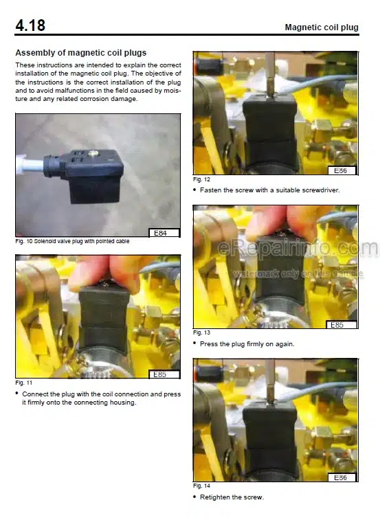
Magnetic Coil Plug
Deutsch Plug, Series DT And DTM
Telemechanique Switch
Plugs And Terminals In Spring Clamping Technology
Batteries
Battery Maintenance
Main Battery Switch, 150S1
Fuses In Battery Compartment
Can Bus Overview
Id Nodes, Overview And Fusing
Control Panels Operator’s Stand, 106B1, 106B2 And 106B3
Modules CR2012, Operating Consoles
Fuse, Multi-Function Display
Control Panel Contact Pressure, 100B10 And 100B11
Control Console For Auxiliary Control 100B5
Control Panel, 100B9
Control Panel Rear Right, 100B3 And 100B8
Control Panel Rear Left, 100B2 And 100B7
Control Panel Front Right, 100B4
Control Console Front Left, 100B1
Central Electrics, 106.1 B1
Modules CR2012, Central Electrics
Travel Pump High Pressure Sensor, 290.1 S2
Hydraulic Oil Temperature Sensor, 290.1 S1
Water Sprinkling System
Limit Switch On Scraper, 214.2S1 And 214.2S2
Rope Sensors For Height Control, 226.5R2 And 226.5R1
Rope Sensors For Steering, 264.6R1 And 264.6R.2
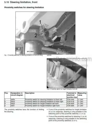
Proximity Switches, Height Limitation
Valve Block (Wording Valve)
Pressure Sensor For Conveyor Belt Drive, 290.1 S3
Temperature Control Valve For Fan Circuit, 216Y1
Fan Circuit Pressure Sensor, 290.1S4
Clutch Pressure Sensor, 290.2S1
Pressure Sensor For The Scraper Flap, 290.2S4
Pressure Sensor For Hold-Down, 290.2S3
Pressure Sensor For Wording Hydraulics, 290.2S2
Hydraulic Temperature Switch, 290S4
Hydraulic Oil Filter Differential Pressure Switch, 290S1 To 290S3
Coolant Level Sensors, 170.1S2 And 170.1S4
Travel Speed Sensor 206.7S1
Solenoid Valve Travel Pump, 206.7Y1
Solenoid Valve Differential Lock, 206.6Y2
Solenoid Valve Brake, 206.6Y3
Solenoid Valve Speed Range Selection, 206.6Y1
Solenoid Valve Conveyor Belt Pump, 238.9Y1
Modules In Engine Compartment, CR2031
Module, CR2031
Module CR2012
Electronic Control Units
Machine Control CR0505
-CAN-BUS, PARAMETER AND DIAGNOSE
Can Bus Overview
Id Nodes, Overview And Fusing
Id-Nodes, Inputs
Id-Nodes, Outputs
Multi-Function Display
Error Messages, Multi-Function Display
Multi-Function Display, Setup
Adjustment Parameters Overview
Menu Option, Tuning Parameters
Menu Option, Check Input Output
Menu Option, Display Adjustment
Menu Option, Can-Bus
Menu Option, Machine States
Menu Option, Rs232
Side Doors, Setup
Milling Drum
Steering, Joysticks
Steering, Pistons
Steering, Adjust Potentiometer
Steering, Central Position Calibration
Steering, Pistons Position Limit
Steering, Front-Rear Link
Steering, Front Prop. Solenoid Valve
Traveling, Joysticks Potentiometer
Traveling, Softgear
Traveling, Engine Load Manager
Traveling, Time Ramps
Traveling, Var. Displ. Pump
Traveling, Var. Displ. Motor
Pause, Time In Sequence
Pause, Time Out Sequence
Columns, Levelling Wire Sensor
Columns, Levelling Slope Sensor
Columns, Speed
Columns, Calibration Levelling Sensor
Columns, Left Column Prop. Valve
Columns, Right Column Prop. Valve
Conveyor, Potentiometer
Conveyor, Var. Displ. Pump
Backdoor, Set-Up
Backdoor, Solenoid Valve
Fan
Fan, Solenoid Valve
Check Input Output
Can Bus, Scan
Can Bus, Change Node Id
ID Nodes, Overview And Fusing
Machine States
-ENGINE ELECTRICS
Engine Control Unit
Pin Assignment
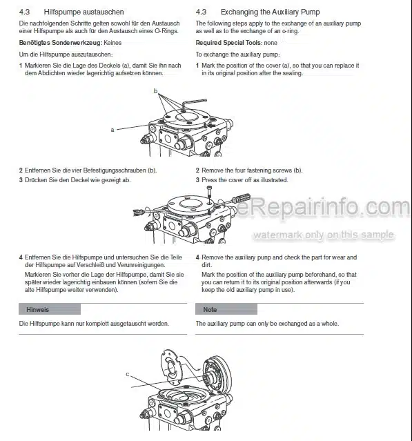
Diagnose With Serdia
Can Bus Overview
Diagnose With Can-Bus
Error Messages, Multi-Function Display
Diagnostic Interface, XMB
Emr3 List Of Fault Codes
Sensors
Oil Pressure Sensor
Fuel Temperature Sensor
Charge Air Temperature – Charge Air Pressure Sensor
Coolant Temperature Sensor
Coolant Level Sensors, 170.1 S2 And 170.1S4
Speed Sensor For Diesel Engine
Preheating System
Sensor, Water In Fuel, 170.1 S3
Air Filter Vacuum Switch, 170.1S1
Generator
Replacing The Voltage Regulator
Electric Starter
-ENGINE
Diesel Engine
Engine Description TCD 2015 V 8 Cylinder
Lubrication Oil Circuit TCD 2015
Coolant Circuit TCD 2015
Fuel Circuit TCD 2015
Injection System (MVS) TCD 2015
Exhaust Gas Recirculation TCD 2015
Wastegate – Charge Pressure Controller On TCD-Engines
Adjusting The Valve Clearance
Check The Engine Oil Level
Changing Engine Oil And Oil Filter Cartridges
Check The Coolant Level
Change The Coolant
Checking The Thermostat In Disassembled State
Cleaning The Engine
Check, Clean The Water Separator
Change The Fuel Pre-Filter Cartridge
Change The Fuel Filter Cartridge
Checking, Replacing The Generator V-Belt
Service The Combustion Air Filter
Intercooler, Draining Oil And Condensation Water
Check Fastening Of Engine / Turbocharger / Combustion Air Hoses
Engine Conservation
General Trouble Shooting Chart TCD 2015
Special Tools, Deutz Engine (TCD 2015)
-MILLING DRIVE, MECHANICS
Milling Drive
Checking, Replacing The Milling Drum V-Belt
Change The Oil In The Milling Drum Reduction Gear
Oil Change In Milling Drum Bearing
Checking/Replacing Cutting Tools, Scraper
Replacing Bases/Holders
Lubricating The Milling Drum
Lubricating The Dry Clutch
Checking The Wear Of The Friction Lining
Friction Lining / Replacing The Outer Discs
-CONVEYOR BELTS, MECHANICS
Conveyor Belts
Checking, Tightening The Conveyor Belts
Checking The Safety Ropes
Lubricating The Conveyor Belts
Folding / Unfolding The Loading Conveyor Belt
-TRAVEL DRIVE, MECHANICS
Travel Drive
Checking The Track Plates
Retightening The Track Shoe Fastening Screws
Checking The Track Drive
Lubricating The Travel Drive
Lubricating The Steering System
Oil Change In Track Drive Gear
-PUMP TRANSFER CASE
Transfer Case
Check The Oil Level In The Pump Drive Gear
Change The Oil In The Pump Drive Gear
-HYDRAULICS
Service Training Bomag Road Milling Machines – Hydraulics
Fault Display
Travel System – Service Training
Conveyor Belt Drive
Working Hydraulics
Fan Drive
Electric Pump For Auxiliary Control (Additional Valves)
-SUPPLIERS DOCUMENTATION
Steering And Working Pump
Travel Pump
Conveyor Belt Pump
Travel Motor
Travel Gear
Conveyor Belt Motor
Sprinkling Pump
-CIRCUIT DIAGRAMS
Hydraulic Diagram
Wiring Diagram
What you get
You will receive PDF file with high-quality manual on your email immediately after the payment.




Reviews
There are no reviews yet