


Factory Service Manual For Toyota Forklift. Manual Contains Illustrations, Instructions, Diagrams For Step By Step Remove And Install, Assembly And Disassembly, Service, Inspection, Repair, Troubleshooting, Tune-Ups.
Format: PDF
Language: English
Pages: 513
Number: CE329-CD (february 2003)
Bookmarks
Searchable
Wiring Diagrams
Model
Toyota Forklift
7FBE10
7FBE13
7FBE15
7FBE18
7FBE20
Contents
-GENERAL
Vehicle Exterior View
Vehicle Models
Frame Number
How To Use This Manual
Operating Tips
Standard Bolt & Nut Tightening Torque
High Pressure Hose Fitting Tightening Torque
Recommended Lubricant Quantity And Types
Lubrication Chart
Periodic Maintenance
Periodic Replacement Of Parts And Lubricants
-BATTERY
Battery Compartment And Required Weight
Service Standards
Display
Troubleshooting
Battery Assy
-CHARGER (OPT)
General
On-Vehicle Charger
Off-Vehicle Charger
-CONTROLLER
General
Specifications
Components
Before Repair
Connector Inspection
Controller
Display
Direction Switch
Accelerator Potentiometer Adjustment
Brake Switch Adjustment
Material Handling Lever Switch Adjustment
-MULTI-DISPLAY FUNCTIONS
Multi-Screen Display
General Functions
Diagnosis
Mask Functions
-TROUBLESHOOTING
Before Troubleshooting
Troubleshooting Method
SST Setting Method
Diagnosis Code List
When An Error Code Is Displayed
When No Error Code Is Displayed
-MOTOR
Drive Motor
Pump Motor
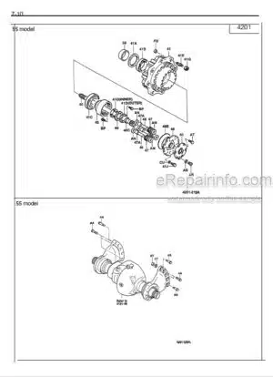
-DRIVE UNIT & FRONT AXLE
General
Specifications
Components
Tires – Wheels
Front Axle Hub & Drive Unit
-REAR AXLE
Rear Axle Assy
Rear Axle Hub
Rear Axle Cylinder Assy
-STEERING
General
Specifications
Components
Steering Wheel – Mast Jacket
Hydrostatic Steering Valve Assy
Inspect And Adjust The Relief Pressure
Priority Valve
-BRAKE
General
Specifications
Components
Disc Brake
Brake Disc Wheel
Brake Pedal
Parking Brake
-BODY & FRAME
Components
Battery Hood Assy
Counterweight
Operator’s Seat
Fuses
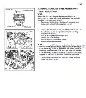
-MATERIAL HANDLING SYSTEM
Hydraulic Circuit
Components
Return Filter
Natural Drop Test
Natural Forward Tilt Test
Oil Leak Test
-MAST
V Mast Assy
Chain
Fork
SV – FV – FSV Mast Assy
Lift Cylinder Rod Shim Adjustment (Prevention Of Uneven Lifting)
-CYLINDER
Lift Cylinder (V – SV) – Rear Lift Cylinder (FV -FSV
Flow Regulator Valve (V – SV – FV – FSV)
Safety Down Valve (V – SV – FV – FSV)
Front Lift Cylinder (FV – FSV)
Tilt Cylinder
-OIL PUMP
General
Components
Removal – Installation
Disassembly – Inspection
Test Method
Reassembly
-OIL CONTROL VALVE
General
Specifications
Components
Oil Control Valve For Vehicle With SAS (Opt)
Oil Control Valve Assy
Relief Pressure Adjustment
Lift Lock Unlocking Bolt (Opt)
Control Valve Lever Assy
-SAS FUNCTIONS (OPT)
General
Components
For Repair Work
Steering Knob Synchronizer Valve
Tire Angle Sensor
Tilt Angle Sensor
Load Sensor
Mast Lifting Height Switch
Matching
Cautions On Modifying Vehicles
-APPENDIX
SST List
Service Standards
CPU Board Connector
Connector Drawing
Connecting Diagram
Electric Wiring Diagram
What you get
You will receive PDF file with high-quality manual on your email immediately after the payment.


Reviews
There are no reviews yet