Factory Service Repair Manual For Terex Atlas 1504 LC, 1604 LC Excavator. Tons of illustrations, instructions, diagrams for step by step remove and install, assembly and disassembly, service, inspection, repair, troubleshooting, tune-ups.
Format: PDF
Language: English
Pages: 456
Bookmarks: Yes
Searchable: Yes
Number:
Wiring Diagrams: Yes
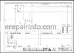
Hydraulic Diagrams: Yes
Model
Terex Atlas
1504 LC
1604 LC
Contents
- – Technical data
- – General information on hydraulics
Introduction
Explanation of symbols and bases of calculation - – Cab Serial
General view of cab
Right switch panel
Left switch panel
Special equipments
Display and controls
Description of the starting procedure - – Hydraulics
Servo control unit
Distributor valves VW
Design
Directional control valve VW / for cylinder implement
Exploded view
Combined relief and makeup valve as secondary valve
Functional description
Operation as a pressure relief valve
Operation as a makeup valve
Control block
Servo unit (Folding jib, slewing, lifting/lowering, bucket/grab)
Structure
Function
Variable Displacement Pump HPR /
Circuit diagram
Functional description
Loadsensing controller
Electrical pressure control valve
Technical description
Loadsensing controller
Electrical pressure control valve
Connection and gage port diagram
Basic design of rotating goup
Basic design of port
Basic design of control system
Slewing motor HMFP
Arrangement
Working gage and connection ports
Arrangement
Circuit diagram
Secondary valve with pressure cut in stage
Diagram
Exploded view of valve plate housing
Functional description
Technical description
Directional control valve
Priority swing drive function
Torque control (TCvalve)
High pressure relief and make up valves with relief pressure step up VD
Feed valves
Variable displacement motor HMV
Circuit diagram
Functional description
Connection and gage port diagram
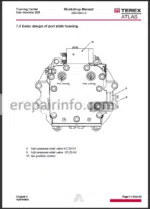
Basic design of port plate housing
Basic design of rotating group
Brake valve
Variable drive motor with automatic control system
Driving pressure below regulating point
Automatic engine idle system
Thermostat valve
Restrictor
Main rotation connection
Rotation connection and rotary transmission leadthrough
Maintenance of the rotary connection
Line break protection
Arrangement
Valve
General
Arrangement
Operation
Jiblowering
Hydraulic diagramsLC,LC
Hydraulic hammer equipment toltr
Hydraulic diagram - – Adjusting instructions and tables for
Safety instructions for adjustment work
Adjustment table
Adjusting instruction
Measuring unions
Bleeding the system
Bleeding hydraulic fluid tank
Bleeding hydraulic pump
Bleeding valve caps
Fuel admission pressure
Engine speed control
Speed measurement
Maximum engine speed
Bowden cable play
Mechanical stop
Speed adjusting lever
Checking
Setting
Testing speed
Teachin the electronic box
Load limit regulating valve
Engine speed
Maximum engine speed
Minimum engine speed
Four points on the speed characteristic
Error diagnosis
General notes
Troubleshooting table
LED
Emergency shift
Pilot control
controller
Return line control block
Pressure cutoff device
Secondary valves
Raising pressure
Adjusting secondary valve
Adjusting pressure
Secondary valve “slewing”
Adjusting secondary valve “slewing”
Adjusting brake pressure
Adjusting the pressure control characteristic
Adjusting TCcharacteristic valve
Pressure cutoff valve
Return flow throttle
Return flow throttle
Locking/releasing the drive units
Locking the drive units
Releasing the drive units
Adjusting travel motor
Bleeding control valve
Adjusting the dynamic pressure of the braking valve
Line break protection valve, lifting cylinder
Switchpoint of the shutoff piston
Determining switch point of control spool
Adjusting switch point of shutoff piston
Adjusting return flow throttle “lowering”
Secondary valves - – Electric
Code letters, terminal designations
Symbols
Line number codes
Jump-starting, starting with a flat battery
Identification of the „Linde electronic box“
The Linde CEB/ Load Limit Control System
Explanation of the Eprom
Encoding Linde box CEB/
Sensor for water temperature
Fluid sensors
Thermostat switch
Oil pressure switch
Pressure switch for emergency control
Pressure operated switch
Circuit and location diagramsLC,LC - – Engine
Setting of valves
Adjusting instruction
Valve-free play scheme - – Ball rotation connection
Transport and storage
Delivery status
Installation
Lubrification and maintenance
Lubricants
Lubrication intervals for the conveying system
Lubrication intervals for the gearing
Checking the screws
Checking the running system
Starting after the swing angle method - – Slewing gear
Exploded view slewing gearGD/GD
Bolt pre loadings and tightening torques - – Gear box
Exploded view
Installation drawing
Name plate
Notes
Conditions of supply
Shipment
Storage
Installation
Fitting of the hydraulic motor
Installation of the gearbox to the machine
Connection of the brake pipe
Lubrication
Gearbox lubrication
Oil filling
Oil draining
Oil replacement and routine checks
Startup
Maintenance
Disassembling
Lifetime seals check
Reassembly
Important notes before reassembly
Instructions for the installation of the half seals
Break check
Fixture drawings and schemes
Substructure general view
Idler unit - – Cylinder
General view
Assembly
Spherical bearing
Piston rod with brass bush
Cylinder nut O mm, O mm, O mm
Omm Cylinder nut (first design)
Piston
Cylinder assembly - – Air condition system
Safety instructions for work on AC system
Function
Cooling circuit system
Diagram
Description
Refrigerant Reclin
Components
Compressor
Technical Specifications
Diagram
FilterDryer
Evaporator
Diagram
Condenser
Diagram
Connection box
Fuse and relay
Operation
General
Advices to the operator
Maintenance
Weekly checks
Monthly checks
Yearly checks by skilled worker
Renewing the filter-dryer
Cleaning/renewing filter mat of air suction filter - – Air condition system
Troubleshooting
General troubleshooting
System does not work
Low power
Description of electrical functions
Conditions for operating the air conditioning system
Switching on
Detailed troubleshooting
Circuit diagrams
Connection box
System - – Maintenance
Safety instructions for maintenance
Renewing hydraulic fluid filter element
Renewing mesh strainer fuel filter
Renewing fuel filter
Changing engine oil, renewing engine oil filter
Maintenance schedule
Lubrication ponts of excavator
Lubricants - – Miscellaneous
Centaflex coupling
Centaflex Type Hdesign and special features
Technical data and dimensions of Centaflex Type H
Assembly instructions for Centaflex Type H
Repair Instruction for Welded Assemblies
Introduction
Service consultation
Area of application
General problems
Damage evaluation
General
Course of crack
Consulting the Service organization
General
Doubler of metal sheet
Drawings / Examples
Preparing the repair
Cleaning
Drilling
Grinding
Preheating the welding area
Qualification of the welding personnel
Selecting the filler metal
Welding wire selection
Stick electrode selection
Repair sequence
Followup work
What you get
You will receive a PDF file with high-quality manual(s) on your email immediately after the payment.


Reviews
There are no reviews yet