Repair Manual For New Holland FX30, FX40, FX50, FX60 Forage Harvester. Illustrations, instructions, diagrams for step by step remove and install, assembly and disassembly, service, inspection, repair, troubleshooting, tune-up.
Format: PDF
Language: English
Pages: 1096
Bookmarks: Yes
Searchable: Yes
Number: 87342127
Wiring Diagrams: Yes
Hydraulic Diagrams: Yes
Model
New Holland FX30, FX40, FX50, FX60
Contents
- – General Information
Introduction
Important Information
–General Instructions
Shimming
Rotating Shaft Seals
–Ring Seals
Sealing Compounds
Bearings
Cotter Pins
Protecting The Electronic / Electrical Systems During Charging Or Welding
–Spare Parts
Tools
Safety Regulations
Accident Prevention
— Safety Rules
General Guidelines
Start-Up
Engine
Electrical System
Hydraulic Systems
Wheels And Tyres
Removal And Re-Fitting
–
Explanation Of Machine Serial Number
Conversion Chart
Hardware Tightening Torques
Drive Line And Components
Lubricants To Be Used - – Engine
— Iveco Engine F3A – General
—Walk Around The Engine
Left Side View
Right Side View
Front View
Rear View
Top View
–
The Iveco Engine
Engine Block And Cylinder Liners
Crankshaft
Crankshaft Sealing Rings
Connecting Rods
Pistons
Camshaft
Timing System
Flywheel
Auxiliary Drivebelt
Lubrication
— Oil Filter
External Coil
Upstream Mount
Filter Septum
Downstream Mount
Structural Parts
–
Oil Sump
Cooling
—Electronically Controlled Injection System
Electronic Control Unit
—Pump Injector
Filling Stage
Injection Stage
Flow-Back Stage
— Iveco Engine — F3A
General Specifications
Fuel System Data
Main Data
Torque Settings
—Plan Of Tightening Sequence
Sub–Cranckcase
Cylinder Head
Exhaust Manifold
Turbocharger
Heat Exchanger
Engine Oil Sump
Rocker Arm Cover
–
Tools
— Mechanical Troubleshooting
Preliminary Conditions
Engine – DisassemblyAssembly
General Notes
Cranckshaft
Pistons, Pistons Rings And Connecting Rods
Cylinder Head
Oil Pump And , Timing System Intermediate Gears
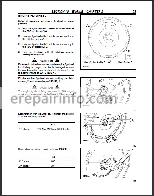
Engine Flywheel
Camshaft
Injectors Pump
Rocker Arm Shaft
Completing The Engine
Assembly Diagram For Fan Drive Belt – Water Pump – Alternator
Cranckcase, Cylinder Liners
Cranckshaft, Bearings
—Selecting Main And Big End Bearing Shells
Main Journals
Crankpins
Selecting Small End Bearings (Pins With Nominal Diameter)
Selecting The Main Bearing Shells (Pins With Nominal Diameter)
Selecting The Main Bearing Shells (Pins With Nominal Diameter)
Selecting The Main Bearing Shells (Ground Pins)
Selecting The Big End Bearing Shells (Pins With Nominal Diameter)
Selecting The Big End Bearing Shells (Ground Pins)
Checking Main Journal Assembly Clearance
Tightening Sequence Of The Screws Fixing The Sub–Crankcase Under The Crankcase
Remove The Sub–Crankcase
Checking Crankshaft End Float
–
Pistons
Connecting Rods
Piston And Connecting Rod – Assembly
Cylinder Head
Tappets And Camshaft
Valve Springs, Rocker Arm Shaft And Rocker Arms
Lubrication System
Cooling Circuit
Fuel Supply
Replacing The Valve Guides
Injector Case – Replacement
Cranckshaft Front Cover Seal – Replacement
Adjusting Clearance Of Rocker Arms To Valves And Pre–Load Of Pump Injector Rocker Arms
Pump Injector – Removal — Refitting
Bleeding The Fuel Supply System
Water Pump – Removal-Refitting
Thermostat – Removel – Refitting
–Iveco Engine F3B – General
Engine Description
Engine Main Components
Cranckshaft
Crankcase Gas Ring
Connecting Rods
Pistons
Cylinder Head
Camshaft
Intake Valve Control
Exhaust Valve Control
Injector–Pump Control
Camshaft Drive
Camshaft Driving
Engine Flywheel
Auxiliary Component Control
Oil Sump
Oil Filter
Fuel Supply
—Main Components Of The Ms62 Edc System
Pump Injector
—-Operation
Filling Phase
Injection Phase
Pressure Reduction Phase
Ms62 Electronic Control Unit13
—Control Unit Operation14
Fuel Batching14
Flow-Rate Correction Depending On Water Temperature
Flow-Rate Correction To Avoid Noises, Fumes Or Overloads
De-Rating
Electronic Injection Spark Advance Check
Speed Regulator
Engine Start–Up
Cold Start–Up
Hot Start–Up
Run Up
After Run
Cylinder Balancing
Synchronisation Search
–
Engine Coolant Temperature Sensor
Fuel Temperature Sensor
Supercharging Air Temperature Sensor
Supercharging Pressure Sensor
Flywheel Sensor
Distribution Sensor
Pre – After Heating Resistance
— Iveco Engine F3B
General Specification
Fuel System Data
Main Data
Torque Settings
Plan Of Tightening Sequence
Tools
Mechanical Troubleshooting
Engine – Disassembly Assembly
General Notes
Crankshaft
Pistons And Connecting Rods
Cylinder Head
Oil Pump And Intermediate Timing Gears
Engine Flywheel
Camshaft
Injectors Pump
Rocker Arm Shaft
Completing The Engine
Crankcase And Cylinder Liners
Crankshaft And Bearings
Selecting Main And Big End Bearing Shells
— Preliminary Appraisal Of Data To Make The Selection
Main Journals
Crankpins
Selecting Small End Bearings (Pins With Nominal Diameter)
Selecting The Main Bearing Shells (Pins With Nominal Diameter)
Selecting The Main Bearing Shells (Pins With Nominal Diameter)
Selection Of Main Half-Bearings (Rectified Pins)
Selecting The Big End Bearing Shells (Pins With Nominal Diameter)
Selection Of Connecting Rod Half-Bearings (Rectified Pins)
Checking Main Journal Assembly Clearance
Remove The Sub–Crankcase
Checking Crankshaft End Float
–
Pistons
Connecting Rods
Piston – Connecting Rod Assembly
Cylinder Head
Valves
Tappets And Camshaft
Valve Springs, Rocker Arm Shaft And Rocker Arms
Lubrication System
Cooling System
Fuel Supply
Valve Guides – Replacement
Injector Case – Replacement
Crankshaft Front Cover Seal – Replacement
Clearance Of Valves To Rocker Arms And Pre-Load Of Pump Injector Rocker Arms
Pump Injector – Removal, Refitting
Bleeding The Fuel Supply System
Water Pump – Removal, Refitting
Thermostat – Removal, Refitting
— Caterpillar Engine
General
New Holland – Caterpillar
Caterpillar Engine
Service / Parts - – Live P.T.O.
— Main Drive Belt Assembly
Tightening Torques And Adjustments
Main Drive Belt Assembly – Remove
Tensioner Pulley Assembly
Cutterhead Drive Pulley
Main Drive Pulley
—Cutterhead Drive Pulley Carrier
Cutterhead Reverse Drive Motor Coupling
Cutterhead Drive Pulley Shaft
–
Main Drive Belt Assembly – Install
Tightening Torques And Adjustments
Special Tools
—Main Drive Gearbox – Remove
Battery Box – Remove
Fuel Reservoir – Remove
–
Rubber Vibration Damper – Replace
—Main Drive Gearbox – Disassemble / Assemble
Splitting The Main Drive Gearbox
—-Lower Gearbox Half – Disassembly / Assembly
Disassembly
Assembly
Intermediate Gear Assembly
Hydro Gear Assembly
—-Upper Gearbox Half – Disassembly / Assembly
Main Hydraulic Clutch – Remove
Output Shaft – Remove / Install
Main Clutch – Install
Connecting The Two Gearbox Halves Together
—Main Clutch – Overhaul
Pressure Hose – Remove / Install
Clutch Plates – Replace
Clutch Seals – Replace
— Main Drive Gearbox Series 5298 > ….
Special Tools
Main Drive Gearbox – Shafts
General
Main Drive Shaft – Remove
Main Clutch – Remove
Main Clutch – Disassemble
Main Clutch – Assemble / Install
Main Drive Shaft – Disassemble
Main Drive Shaft – Assemble
Main Drive Shaft – Install
Main Drive Gearbox – Remove / Install
—Main Drive Gearbox – Disassemble / Assemble
Splitting The Main Drive Gearbox
—-Lower Gearbox Half – Disassemble / Assemble
Disassemble
Assemble
–
Main Drive Gearbox – Assemble - – Transmission
Specifications
Tightening Torques And Adjustments
Special Tools
Gearbox Shafts
Shifting Diagram
—Disassembly Of Traction Gearbox
General
Removal Of Selector Forks And Shifter Shafts
Removal Of Drive Shaft
Removal Of The Countershaft
Removal Of Transmission Main Shaft
Removal Of The Half–Shaft From The Differential
Removal Of The Differential
—Assembly Of Traction Gearbox
Assembly Of The Differential
Assembly Of The Half–Shafts Of The Differential
Assembly Of Transmission Main Shaft
Assembly Of The Countershaft
Assembly Of The Drive Shaft
Assembly Of Selector Shafts And Forks
Calculation Of Shims To Be Installed On The Shafts
Assembly Of The Cover
Specifications
Tightening Torques
—Special Tools
Self-Made Tools
–
Gearbox Shafts
Wd Gearbox – Removal
Wd Gearbox – Components
—Wd Gearbox – Disassembly
Intermediate Shaft
Input Shaft
Output Shaft And Clutch
Clutch Cylinder
—Wd Gearbox – Assembly
Clutch Cylinder
Output Shaft And Clutch – Pre Assembly
Input Shaft – Pre Assembly
Intermediate Shaft – Installation
Input Shaft – Installation
Cover – Installation
Clutch Pre-Assembly – Installation
–
Wd Gearbox – Installation - – Front Mechanical Drive
— Final Drives Fx30
—Final drives – Disassembly
Output shaft
Input shaft
—Final drives – Assembly
Input shaft
End play adjustment
Output shaft
Preload adjustment
— Final Drives Fx40-50-60
Specifications
Tightening Torques
Gearbox Shafts
Wheel Bolt – Replacement
Final Drive – R/ I
—Final Drive D/A
Disassembly
Assembly
– Hydrostatic System
—Hydrostatic Circuit And Components
Circuit
–
Hydrostatic Pump And Motor Identification Plate
—Hydrostatic Pump
Pump Operation
Circuit
Pump Characteristics
Multifunction Valve
—-Servo Valve
System In Neutral
Servo Solenoid Valve Energized
—Hydrostatic Motor
Fixed Displacement Motors
Drive Motor Characteristics
–
Oil Cooler Bypass Valve
Filling And Bleeding The Hydrostatic System
Starting The Hydrostatic System - – Brakes And Control
—Brake System
General
Road Mode
–
Parking Brake Adjustment
—Replacement Of The Brake Linings
Removal
Installation
—Bleeding The Brakes
Bleeding The Left-Hand Side Circuit
Bleeding The Connection Pipe Between The Two Main Cylinders
Bleeding The Right-Hand Side Circuit
—Disassembly And Assembly Of Brake Shoes And Discs
Disassembly Of Brake Shoes
Disassembly Of Brake Discs
Assembly Of Brake Discs
Assembly Of Brake Shoes - – Hydraulic System
— General
—Torque Tables For Hydraulic Components
Union Nuts
Ferrules
—-Metric Fittings
Unions
Connections
Swivel Nut With Ball-Type Nipple
–
Pump Group – Disassembly And Assembly
—Disassembly Of The Pump Group
Removal Of The Triple Pump From The Hydrostatic Pump
Splitting Of The Triple Pump
Assembly Of The Pump Group
Installation Of The Pump Group To The Hydrostatic Pump
— Work Hydraulics – Attachment Height Control
—Circuit Diagrams
Work Hydraulics – Attachment Height Control
–
Hydraulic Oil Reservoir
Low Pressure Filter
Breather
High Pressure Filter
—Non-Return Valve
Function
—Work Hydraulics Pump
Specifications
–
High Pressure Relief Valve
—Attachment Height Control Valve (Emr)
Neutral Position
Attachment Lifting Position
Attachment Lowering Position
Pressure Relief Valve H
Emergency Hand Buttons
Specifications
—Attachment Compensation Valve
Specifications
Transport Mode
Compensation Mode
Stubble Height Mode
—Pressure Sensor
Specifications
—Hydropneumatic Accumulators
Filling
Attachment Lift Cylinders
— Work Hydraulics – Base Unit
Circuit Diagrams – Base Unit
—Stack Valve
Repair Of Control Valves
—Load Sensing Valve
System In Neutral
—Cutterhead Reverse Drive Motor
Specifications
–
Spout Rotation Pressure Relief Valve
—Spout Rotation Motor
Specifications
—Quick-Release Couplings
Specifications
—Spout Lift Cylinder
Cylinder Disassembly And Assembly
Reinstallation Of Spout Lift Cylinder
— Steering Hydraulics
Circuit Diagrams — Steering Hydraulics
—Steering Hydraulics Pump
Specifications
—Steering Valve
Special Tools
Steering Valve – D/A
—Steering Cylinders
Disassembly And Assembly
Toe-In Adjustment, Steering Ball Joints, Steering Wheel Stops
— Low Pressure Hydraulics
Circuit Diagrams – Low Pressure Hydraulics
—Low Pressure Hydraulic Reservoir
Oil And Filter Change Procedure
Oil Pressure Check Procedure
Filling The System When (Re)Installing The Low Pressure Pump
Filling The System After (Re)Installing The Main Drive Transfer Gearbox
—Low Pressure Pump
Specifications
–
Low Pressure Valve
Main Drive Belt Tensioning Cylinder
Spout Deflector Cylinder
— High–Flow Hydraulics
Circuit diagrams – High-Flow hydraulics
– Cab Climate Control
Correct Use Of The Airconditioning System
Storage Maintenance
—Air Conditioning Circuit
Components
—Specifications
Refrigerant
Compressor
Compressor Clutch
Circuit Parameters
Low Pressure Switch
High Pressure Switch
Filter-Drier
—Compressor Clutch Replacement
Clutch Removal
Clutch Installation
–
Ventilation Unit - – Electrical System
— General
—General information
Wires
Color code
Wire identification
Fuses
Symbols
Relays
–
Connectors
— Wiring Diagrams Fx North America
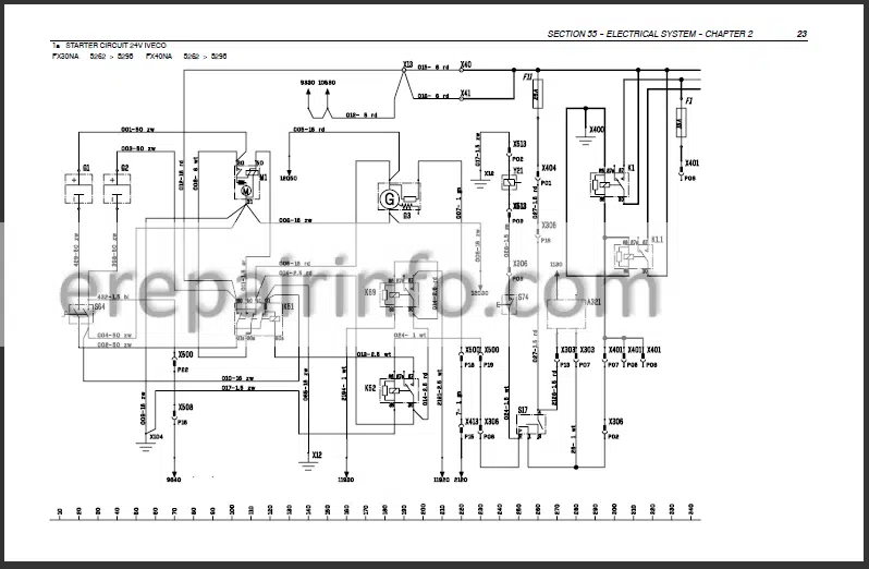
Wiring Diagrams Fx Na
— Can Network Basics
Can Network Basics
—General Layout Electronic System
Electronic Components
Conclusion
—Electronic System Layout
Input
Output
Analog Signals (From Input Or To Output)
Digital Information
Interfaces
Software
Calibrations
Additional Info:
—Can Spy
Decimal And Hexadecimal Counting
Decimal
Hexadecimal
How To Use The Can Identifiers
How To Enter Can–Spy
Can–Spy In Practice
—Error Codes Messages
Wiring Checking Procedure
–
Fault Finding Routine
— Calibration
General
Special tools
—Machine calibration with EST tool
Configuration Item Selection screen
Maximum Handle position calibration
Minimum forward pump current calibration
Minimum reverse pump current calibration
Vehicle Configuration
— Software Update
Software Revision
Software Update With Est Tool
— Troubleshooting
Machine Error Messages
—Attachment Height Control Error Messages
Error Reports
–
Caterpillar Error Messages
Cursor Error Messages
List Of Can Identifiers
Detailed Analisys Per Function
Electric Conditions, Engine Running Or Not Running
Engine Protection
Harvest Mode
Engine Acceleration
Cutterhead Engagement
Feed Rolls Forward Engagement
Feed Rolls Reverse Engagement
Power Reverse
Four-Wheel Drive
Spout Rotation
Raise / Lower Spout
Spout Deflector
Reverse Cutterhead
Auxiliary Front Hydraulics
Auxiliary Rear Hydraulics
Air Conditioning
Silage Additives Application
Knife Sharpening
Adjust-O-Matic Routine
Crop Processor
Metal Detector Operation And Troubleshooting
Attachment Height Control
Ground Speed
High Flow Hydraulics
Rotary Screens
Rotary Screen Brushes
Caterpillar Engine
Can Network
Auto Pilot
Automatic Greasing
Cursor Engine Fx30-40-50
Feedroll Speed
– Product Feeding
— Feed Rolls
—Metal Detector Roll
Removal
Disassembly
—-Metal Detector Components – D/A
Disassembly
Assembly
Assembly
Installation
—Smooth Roll
Removal
Installation
—Upper Feed Rolls – R/I
Before Removal
Removal Of The Upper Feed Rolls As A Complete Assembly
Removal Of The Upper Feed Rolls As Separate Components
Replacing Wear Plates On The Upper Feed Rolls Frame
Installation
— Hydroloc Gearbox
—Hydroloc gearbox – R/I
Removal
Installation
–
Gearbox shafts
Specifications
—Hydroloc gearbox — D/A
Alternative drive shaft
Transfer shaft
Upper feed rolls drive shaft
Selector shaft
Smooth roll drive shaft
Metal detector roll drive shaft
Reinstall the alternative drive shaft
Install seals and covers
— Attachments Drive Gearbox
—Attachments Drive Gearbox – R/I
Removal
Installation
–
Gearbox Shafts
Specifications
—Attachments Drive Gearbox – D/A
—-Assembly
Idler Shaft
Input Shaft
Transfer Shaft
Attachment Drive Shaft
Idler Shaft – Re-Installation
— Upper Feed Rolls Drive Gearbox
Special Tools
—Upper Feed Rolls Drive Gearbox – R/I
Removal
Installation
–
Gearbox Shafts
Specifications
—Upper Feed Rolls Drive Gearbox – D/A
—-Assembly
Upper Feed Rolls Drive Shaft
Front Upper Feed Roll Drive Shaft f
Rear Upper Feed Roll Drive Shaft
Re-Install The Upper Feed Rolls Drive Shaft
Seals And Cover - – Chopping
— Cutterhead
Splitting Of Components
—Rotor And Bearings – R/I
Removal
Assembly
–
Shearbar – R/I
—Shearbar Support – R/I
Removal
Installation
— Cutterhead Gearbox
—Cutterhead Gearbox – R/I
Removal
Installation
—Cutterhead Gearbox – D/A
Oil Cooler – D/A
—-Gearbox – Disassembly
Input Shaft
Output Shaft
—-Gearbox – Assembly
Input Shaft
Output Shaft
Backlash
– Ejection
— Blower Gearbox
Inspection Between Cutterhead And Blower
Blower – R/I
Blower Gearbox – R/I
—Blower Gearbox – D/A
Disassembly
Assembly
Input Shaft
Output Shaft
Adjusting The ShimmingWhat you get
You will receive PDF file with high-quality manual on your email immediately after the payment.






Reviews
There are no reviews yet