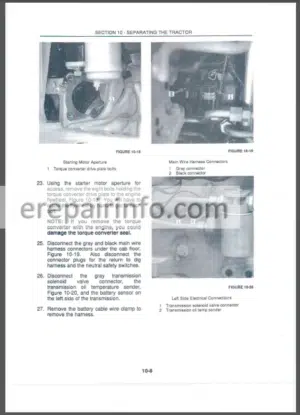
Repair Manual For New Holland LS140 LS150. Illustrations, instructions, diagrams for step by step remove and install, assembly and disassembly, service, inspection, repair, troubleshooting, tune-up.
Format: PDF
Language: English
Pages: 546
Bookmarks: Yes
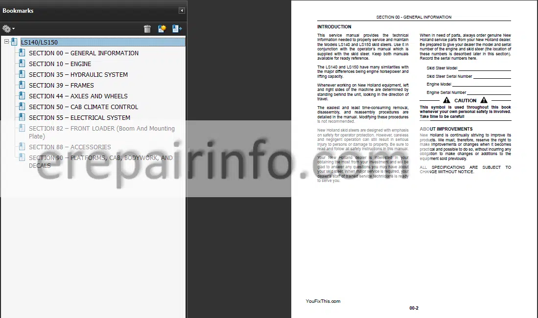
Searchable: Yes
Wiring Diagrams: Yes
Hydraulic Diagrams: Yes
Model
New Holland LS140, LS150
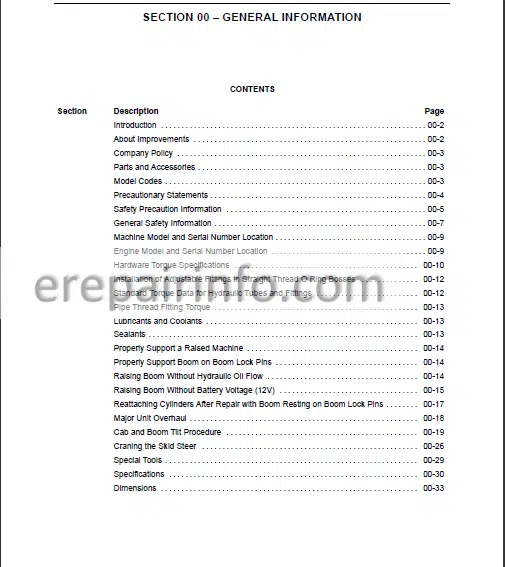
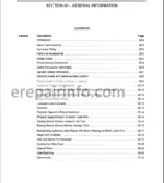
Contents
- – General Information
Introduction
About Improvements
Company Policy
Parts And Accessories
Model Codes
Precautionary Statements
Safety Precaution Information
General Safety Information
Machine Model And Serial Number Location
Engine Model And Serial Number Location
Hardware Torque Specifications
Installation Of Adjustable Fittings In Straight Thread O Ring Bosses
Standard Torque Data For Hydraulic Tubes And Fittings
Pipe Thread Fitting Torque
Lubricants And Coolants
Sealants
Properly Support A Raised Machine
Properly Support Boom On Boom Lock Pins
Raising Boom Without Hydraulic Oil Flow
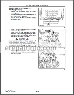
Raising Boom Without Battery Voltage (V)
Reattaching Cylinders After Repair With Boom Resting On Boom Lock Pins
Major Unit Overhaul
Cab And Boom Tilt Procedure
Craning The Skid Steer
Special Tools
Specifications
Dimensions - – Engine
Engine Component Descriptions
Engine Model And Serial Number Location
Safety Precautions
General Engine Specifications
Torque Specifications
Engine Components Electrical Diagram
Engine Removal
Engine Disassembly Sequence
Engine Component Maintenance
Valve Seat
Cylinder Block
Piston And Piston Rings
Connecting Rod
Bearing Holder
Front Crankshaft Bearing (Bushing)
Crankshaft
Flywheel And Ring Gear
Camshaft Assembly
Camshaft Gear And Bearing Assembly
Timing Gear
Oil Pump
Port Block
Oil Filter
Water Pump Assembly And Thermostat Housing
Thermostat
Governor
Governor Operation
Engine Reassembly Sequence
Crankshaft And Bearing Holder Assembly
Rear Oil Seal
Backplate/Flywheel Housing
Flywheel
Piston And Connecting Rod
Oil Intake And Oil Strainer
Oil Sump
Dipstick And Tube
Front Plate
Idler Gear And Oil Pump
Timing Gear Case
Crankshaft Pulley
Injection Pump
Spill Timing Procedure
Reinstallation Of Engine Into Skid Steer Frame
How To Operate The Engine After Overhaul
Cooling System
Cooling System Operation
Water Pump Assembly And Thermostat Housing
Radiator
Fuel System
Fuel Specifications
Diesel Fuel
Diesel Fuel Storage
Fuel System Components
Fuel Guage
Cold Start Aid
Fuel Filter System
Priming The Fuel System
Fuel System Testing
Fuel System Components
Fuel Injection Timing
Miscellaneous Engine Electrical - – Hydraulic System
Hydraulic System Compatibility
Boom Cylinder Pivot Pins
Boom Cylinder Pivot Pin Location And Machine Usage
Control Valve Power Beyond
Auxiliary Boom Hydraulics Troubleshooting
Hydraulic System Testing
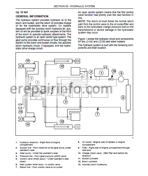
Hydraulic System Oil Flow (Neutral Position)
Control Valve
Main System Pressure Tests
Checking Main System Pressure At Boom Cylinders
Checking Main System Pressure At Bucket Cylinders
Checking Main System Pressure At Auxiliary Boom Hydraulic Quick Couplers
Boom Circuit Relief Valve Test
Gear Pump Flow Efficiency Test
Boom And Bucket Spool Lock Solenoid Test
Hydraulic, Hydrostatic System Air Ingress Test
Control Valve Specifications
Control Valve
Control Valve Parts
Hydraulic Pump Specifications
Hydraulic Pump
Hydraulic Pump Parts
Hydraulic Pump
Cylinders, Boom And Bucket
Boom Cylinder
Boom Cylinder Parts
Boom Cylinder
Bucket Cylinder
Bucket Cylinder
Pedal Controls
Pedal
Hydraulic Cooling, Filter, Reservoir System
Filter System
Filter
Base
Oil Cooler
Oil Cooler Reassembly - – Frames
Cab And Rops - – Axles And Wheels
Axles
Axle Housing
Axle Parts
Final Drive
Final Drive Parts
Tires/Wheels
Tire And Track
Loader Boom Stop Adjustment - – Cab Climate Control
Heater/Defroster - – Electrical System
Definition Of Terms
Adapting Attachments Requiring V Electrical Power
Specifications
Electrical Diagram
Advanced Warning System
Electronic Instrument Cluster (Eic)
(Eic) Electronic Instrument Cluster Front Panel
Eic Functional Groups
Engine Preheat
Automatic Shutdown
Operating Mode
Broken Alternator/Water Pump Belt Warning
Fuel Level
Eic Interlocks
Eic Lock Mode
Eic Engine Preheat
Troubleshooting
Advanced Warning System (Aws)
Eic Board Self Test
Diagnostic And Setup Modes
Arrow, Open Book, And Audible Alarm Test
Diagnostic Mode Eic Circuit Tests
Eic Setup Mode
Electronic Instrument Cluster (Eic) And Starter Circuits
Blown Fuse Symptom And Testing
Testing Other Eic Functions
Eic Board Reading Accuracy
Eic Board Claims Warranty
Electrical Circuits
Seat Switch Circuit To Eic Board
Seat Belt Switch Circuit To Eic Board
Ignition Switch Circuit To Eic Board
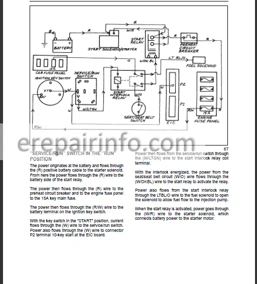
Cranking Circuit (Starter Motor)
“Service/Run” Switch In The “Run” Position
Cranking Circuit Ground
Operating Conditions “Service/Run” Switch In The “Service” Position
Service/Run” Switch In The “Service” Position
Cranking Circuit Ground
Start Relay Operation
Start Relay Circuit
Start Relay Ground Circuit
Start Interlock Relay Operation
Start Interlock Circuit
Start Interlock Ground Circuit
Start Circuit
Battery
Battery R
Eic
Ignition (Key) Switch Wiring
Ignition (Key) Switch
Cab Fuse Panel Wiring
Cab Fuse Block And Panel
Service/Run Switch Wiring
Seat And Seat Belt Switch Wiring
Seat Switch
Seat Belt Buckle And Switch
Road Light And Work Light Switch Wiring
Road Light And Work Light Switch Removal
Road Light And Work Light Switch
Engine Fuse And Relay Panel
Accessory Relay
Preheat Circuit Breaker Wiring
Preheat Circuit Breaker
Start Interlock Relay Wiring
Start Interlock Relay
Engine Fuse Panel Wiring
Engine Fuse Block
Alternator Excite Resistor Wiring
Alternator Excite Resistor
Start Relay Wiring
Start Relay
Preheat Relay
Preheat Glow Plug
Fuel System Components
Electric Fuel Pump
Electric Fuel Pump
Fuel Shutoff Solenoid
Fuel Shutoff Solenoid Testing
Replacement Of Fuel Shutoff Solenoid
Air Filter Restriction Indicator Switch
Engine Coolant Temperature Sender
Engine Oil Pressure Switch
Hydrostatic Charge Pressure Switch
Hydraulic Oil Filter Restriction Switch
Hydraulic Oil Temperature Sender
Boom/Bucket Control Valve Spool Lock Solenoids
Wire Harness
Main Wire Harness Installatio
Road/Work Lights
Alternator
Charging Circuit
Alternator Service Specifications
Alternator System Testing And Troubleshooting
Service Precautions
Initial Tests
Alternator
Starter
Starter Motor Troubleshooting
Starter Motor
Starter
Miscellaneous Engine Components
Glow Plug
Fuel ShutOff Solenoid - – Front Loader (Boom And Mounting)
Buckets
Boom Lock Pins And Linkage
Boom
Attachment Mounting Plate
Boom And Cylinder Pivot Pins
Boom And Cylinder Pivot Pin Location And Machine Usage
Boom And Cylinder Pivot Pins Size
Pallet Fork
Utility Fork
Bucket Cutting Edge (Replacement)
Bucket Latch Plate Installation Procedure
Dirt Tooth Kit
Bucket Tooth Spacing
Boom Lock Pin/Linkage
Boom Lock Pin/Linkage
Boom, Upper And Lower Link
Front Boom Mounting Plate Pivot Hub Replacement
Boom, Upper And Lower Link
Attachment Mounting Plate
Attachment Mounting Plate
Repair/Rebuild Mounting Plate
Latch Lever And
Attachment Mounting Plate Parts
Checking Procedure For Buckets And Attachments
Checking Procedure
Checking The Loader Faceplate - – Accessories
Adapting Attachments Requiring V Electrical Power
Hydraulic System Compatibility
Arm Pads For Cab Side Panels
Armrests For Deluxe Seat
Forearm Rests
BackUp Alarm
Block Heater (Engine)
Electric Power Supply
Exhaust (Engine)
Aspirator Precleaner Muffler
Horn
Shoulder Belt (Seat)
SlowMoving Vehicle (Smv) Sign Kit
Warning Light (Rotary Beacon)
Warning Lights (FourWay Flashers/Turn Signal/Horn) - – Platforms, Cab, Bodywork, And Decals
Seat And Seat Pan Support
Seat
Safety Decals
What you get
You will receive PDF file with high-quality manual on your email immediately after the payment.


Anonymous (verified owner) –
This manual is for a newer model than mine, but it worked for what I needed it for, which was identifying what the warning icons mean.