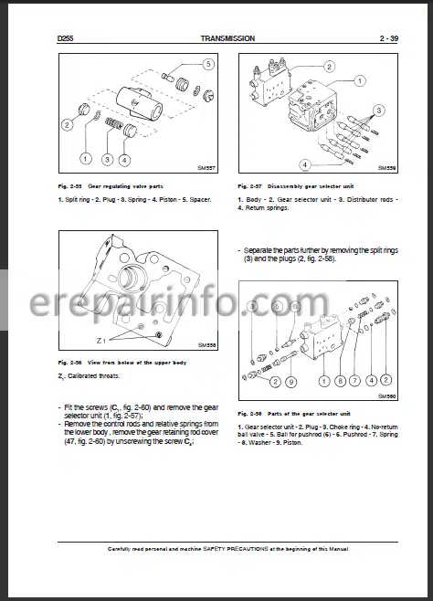
Factory Service Repair Manual For New Holland D255 Crawler Dozer. Tons of illustrations, instructions, diagrams for step by step remove and install, assembly and disassembly, service, inspection, repair, troubleshooting, tune-ups.
Format: PDF
Language: English
Pages: 337
Searchable: Yes
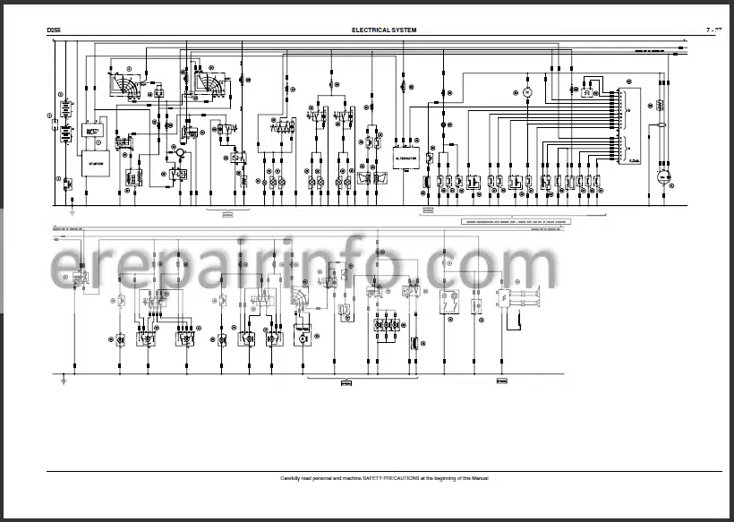
Wiring Diagrams: Yes
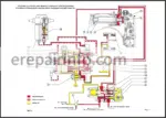
Hydraulic Diagrams: Yes
Model
New Holland D255
Contents
- Generalities
- Engine
- Transmission-Torque Converter
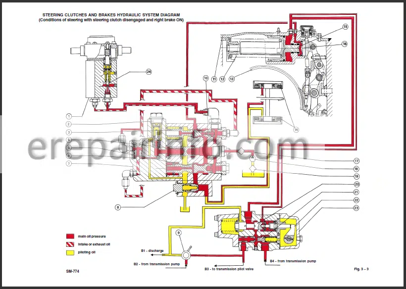
- Steering Clutches – Brakes
- Final Drives
- Undercarriage
- Dozer Equipment
- Hydraulic System
- Electrical System
- Air Conditioning Unit
Full contents
-Generalities
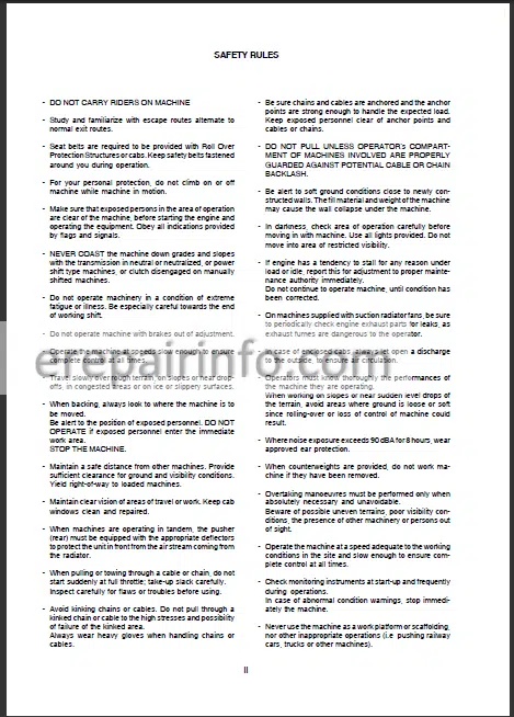
Safety Rules
Technical Data Tables
General Instructions
Diagnostic Checks
Measure Units
Classification Of Standard Parts
Tightening Torques
-Engine
General Specifications
Series “C” Engine Data
Diagrams Of Series “C” Engine
Mounting Of Engine On Frame
Aftercooler Fan Drive System
16 Throttle Linkage
-Transmission
General Description
Troubleshooting
–Converter
Removal
Disassembly
Checking Parts
Converter Safety Valve
–Transmission
Removal
Disassembly Transmission
Disassembly Clutch
Assembly Transmission
Lubrication Oil Pressure Regulating Valve
Relief Valve
Assembly Clutch
–Transmission Distributor
Removal And Disassembly
Checking Parts
–Control Lever
Disassembly
Operating Diagram
Checking Parts
Safety Deflector
–Converter/Transmission Hydraulic Pumps
Disassembly And Testing
Transmission Oil Heat Exchanger
Cleaning And Checking Parts
–Drive Shaft/Converter/Transmission
Disassembly And Testing
Assembly
–Oil Filter Converter – Transmission
–Testing Transmission/Converter On The Vehicle
Testing Gear Selection With Converter In Stall
Checking Transmission-Converter Pressure
Checking Clutch Pressure
Lubricating Oil Pressure
Converter Oil Pressure
Transmission Feed Pressure Check
—
Technical Data
Tightening Torques
Special Tools
-Steering Clutches And Brakes
General Description
Troubleshooting Of Major Malfunctions
–Central Reduction Bevel Gear Set
Disassembly
Assembly
Setting Of Bevel Gear
–Steering Clutches And Brakes
Removal Of Brake Bands
Disassembly
Inspection Of Clutch Packs
Assembly Of Steering Clutches
Installation Of Steering Clutches And Setting
–Brake Cylinder
Steering Clutch And Brake Hydraulic Pump
Inspection Of Components
–Oil Filters
Steering Clutch And Brakes Control Valve
Disassembly Of Control Valve
Inspection Of Components
–Brakes Control Valve
Disassembly
Inspection Of Components
–Control Pilot Valve
Disassembly Of Pilot Valve
Inspection Of Components
–Tests
Check Of Clutch-Brakes Control Valve Pressures
Adjustment Of Brake Pedal
Check Of Brakes System Pressures
—
Specifications And Data
Tightening Torques
Special Tools
-Final Drives And Sprockets
Description
Removal
Disassembly
Inspection Of Sprockets
Assembly
Installation
Specifications And Data
Tightening Torques
Special Tools
-Undercarriage
General Description
Troubleshooting Of Major Malfunctions
–Track Chains
Disassembly
Inspection Of Undercarriage Components
Replacement Of A Damaged Link
–Track Adjustment Mechanism
Disassembly
Setting Of Hydraulic Adjuster Cylinder Relief Valve
Inspection And Adjustment Of Track Chain Tension
–Track Idler Wheels
Removal
Overhaul
Installation And Adjustment
–Track Rollers
Removal
Overhaul
–Track Carrier Rollers
Disassembly
–Lubrication Of Rollers And Track Idler Wheels
–Track Frames
Inspection Of Track Frames
Track Frame Adjustment
Track Frame Pivots
—
Front Suspension
Specifications And Data
Tightening Torque
Special Tools
-Hydraulic System For Angledozer Equipment
–General Description
Rapid Release Valve
–Trouble Shooting
–Hydraulic Oil Tank And Oil Filters
Filters
Removal Of The Tank
–Hydraulic Pump
Removal
Overhaul Of The Control Pump
Pump Overhaul
Reassembly
Flow Testing
–Distributor
Removal
Disassembly And Overhaul
Reassembly
Hydraulic Bench Testing Of Distributor
Checking And Setting The Main Safety Valve On The Machine
—
Arch And Blade Of The Angledozer
Blade Raising And Lowering Control Cylinders
Rapid Release Valves
Ripper
Technical Data
Tightening Torques
Special Equipment
-Electrical System
Safety Rules
Location Of Main Electrical Components
–Fuses
Connection For Engine Starting External Electric Power Source
Electrical System Master Switch
Starter Motor
Engine Starting Key Switch
Engine Cut-Off Solenoid
Back-Up Alarm Pressure Switch
Back-Up Alarm
Diverter Box
Alternator
Right And Left Brake Failure Sensors
Engine Coolant Max Temperature Switch
Air Cleaner Clogging Sensor
Hydraulic Oil Filter Clogging Sensor
Transmission Oil Max Temperature Switch
Engine Oil Low Pressure Sensor
Fuel Level Sensor
Engine Coolant Level Sensor
Engine Oil Low Level Sensor
Transmission Oil Low Level Sensor
Transmission Oil Low Pressure Sensor
Buzzer
EDM Control Module
Air Conditioner Solenoid Switch
Services Solenoid Switch
Diodes Box
Cab Services Solenoid Switch
“Link” Fuses
Starter Safety Solenoid Switch
Wiring Diagram
-Air Conditioning Unit
–Air Conditioning Unit
Operating Instructions
Technical Data
Cab Climate Conditioner
Service Precautions
Tool Connections
Discharging
Refrigerant Charging
Leak Inspection
Special Tools
Troubleshooting
What you get
You will receive PDF file with high-quality manual on your email immediately after the payment.
Reviews
There are no reviews yet