Factory Service Manual And Manual Update For Case Farmall Tractor. Manual Contains Illustrations, Instructions, Diagrams For Step By Step Remove And Install, Assembly And Disassembly, Service, Inspection, Repair, Troubleshooting, Tune-Ups.
Format: PDF
Language: English
Quantity of Manuals: 2
Pages: 628; 84
Number: 84419878A- October 2011 ; 84419878A1- November 2011
Bookmarks: Yes
Searchable: Yes
Wiring Diagrams: Yes
Hydraulic Diagrams: Yes
Model
Case Tractor
FARMALL 55C
FARMALL 65C
FARMALL 75C
Contents
-GENERAL GUIDELINES
General Instructions
Safety Regulations
Tractor Refuelling
-ENGINE
Summary
General Specifications
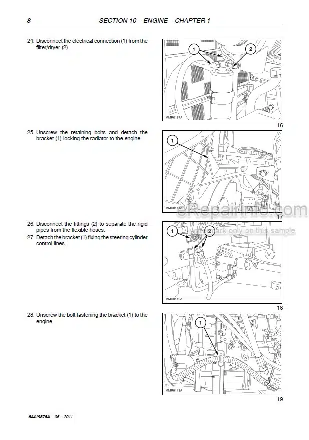
Engine Removal-Installation
Removal-Installation Fuel Tank
Coolant Radiator Removal Installation
Accelerator Control Cable Adjustment
-CLUTCH
Main Data
Torque Specifications
Tools
Sections
Troubleshooting
Removal-Installation Clutch
Clutch Overhaul
Checks And Measurements – Clutch
Adjustments – Clutch Disengagement Levers
Adjustments – Clutch Pedal
Sectional View Of PTO Clutch Servo Control
Description And Operation Of PTO Servo Control
PTO Servo Control Adjustment
PTO Engaged Switch Adjustment
-GEAR TRANSMISSION
Mechanical Transmission
Power Shuttle Transmission
-DRIVELINES
Main Data
Torque Specifications
Sections
Description And Operation
Troubleshooting
Drive Shafts And Guard Disassembly – Assembly
Removal-Installation – Drive Gear Casing
-FRONT AXLE MECHANICAL TRANSMISSION
Main Data
Torque Specifications
Tools
Sections
Removal-Installation
Front Axle
Front Axle Disassembly –
Assembly
Replacing Steering Knuckle Pins And Bearings
Adjustments – Steering Knuckle Bearings
Adjustments – Bevel Drive
Overhaul – Front Differential
Lim-Slip Self-Locking Differential
Checking Leading Wheel Alignment
Disassembly-Assembly -Front Epicyclic Final Drive
-REAR MECHANICAL TRANSMISSION
Main Data
Torque Specifications
Tools
Sections
Description And Operation Troubleshooting
Disassembly-Assembly -Transmission-Gearbox Casing
Adjustments – Differential Lock Engagement Sleeve Position
Adjustments – Bevel Drive
Removal – Installation
Side Gear Casing
Disassembly-Assembly -Drive Wheel Shaft
-POWER TAKE-OFF
Main Data
Torque Specifications
Sections
Description And Operation
Troubleshooting
-BRAKES
Main Data
Torque Specifications
Sections
Description And Operation
Troubleshooting
Removal-Installation – Service Brake
Removal-Installation – Service Brake Pump
Adjustments – Service Brake Pedals Travel
Service Brake Circuit Air Bleeding
-HYDRAULIC SYSTEMS
Rear Mechanical Hydraulic Lift
Open Centre System Auxiliary Control Valves
Open Centre System Auxiliary Control Valves
Front Loader
-STEERING
Main Data
Torque Specifications
Tools
Description And Operation
View Of Hydrostatic Steering Control Valve Components
Troubleshooting
Replacement – Hydrostatic Steering Wheel
Removal-Installation – Hydrostatic Steering Control Valve
Disassembly-Assembly -Hydrostatic Control Valve
Hydrostatic Steering Control Valve Bench Testing
Pressure Relief Valve Testing Steering Control Cylinder Removal – Installation
Steering Control Cylinder Disassembly-Assembly
-CAB HVAC SYSTEM
Safety Regulations
Main Data
Tools
Operating Principles
Conditioning System Components
Cab Controls
Testing Operation And Cooling
Air Conditioning System Maintenance
Troubleshooting
Refrigerant Recovery-Recycling And Evacuation-Charging Stations
Dehydration, Recharging And Refrigeration Check
Checking For And Eliminating Any Gas Leaks
Cab Heating/Air-Conditioning System Removal – Installation
Cab Electric Fan Unit Disassembly – Assembly
Air-Conditioning System Condenser Removal-Installation
– ELECTRICAL SYSTEM
Instruments
Starting System
Charging System
Battery
Electrical Circuits
Wiring Harnesses And Connectors
-PLATFORM, CAB, BODYWORK
Cab
What you get
You will receive PDF file with high-quality manual on your email immediately after the payment.



Reviews
There are no reviews yet