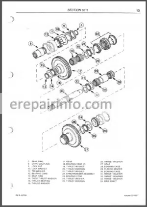
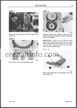
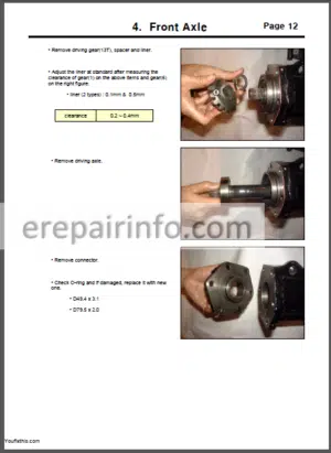
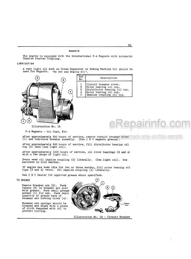
Factory Service Repair Manual For McCormick McCormick F GE-XL Series Tractors. Tons of illustrations, instructions, diagrams for step by step remove and install, assembly and disassembly, service, inspection, repair, troubleshooting, tune-ups.
Format: PDF
Language: English
Pages: 951
Bookmarks: Yes
Searchable: Yes
Number:P/N 3676090M1
Wiring Diagrams: Yes
Hydraulic Diagrams: Yes
Model
McCormick
F 60 GE
F 60
F 70 GE
F 70
F 80 GE
F 80
F 75 GE
F 75
F 75 XL
F 85 GE
F 85
F 85 XL
F 95 GE
F 95
F 95 XL
F 105 GE
F 105
F 105 XL
Contents
- -INTRODUCTION
READING THE MANUAL
Introduction
Structure of the manual-
TRACTOR IDENTIFICATION AND TECHNICAL SPECIFICATIONS
Tractor identification
Weights and dimensions
Engine specifications
WORKING IN SAFETY
Essential rules for accident prevention
Danger decals
Replacing tractor parts
Safe use of the tractor-
PRE-DELIVERY INSPECTIONS AND MAINTENANCE
General information
Inspections before delivery
Routine maintenance guide
CONVERSION TABLES
Length
Area
Volume
Weight
Pressure
Moment of rotation
Temperature
SEALANTS
Types of Loctite sealants
Practical advice
DRIVING TORQUES
GENERAL ASSEMBLY INSTRUCTIONS
Seals
O-rings
Bearings - -ENGINE
PRECAUTIONS AND SAFETY RECOMMENDATIONS
TECHNICAL SPECIFICATIONS
Main Technical Specifications
DRIVING TORQUE VALUES
Standard Torque Values
Recommended Torques
ENGINE TUNING
Introduction
How To Find The Compression Tdc Of Cylinder N°1
Injection Pump Timing - -CLUTCH
PRECAUTIONS AND SAFETY WARNINGS
GENERAL DESCRIPTION
Drawing Of Assembly (Speedfive Version)
Description Of Operation-
Damper (Powershuttle Version)
TECHNICAL SPECIFICATIONS
Main Technical Specifications
INSPECTION, OVERHAUL AND ADJUSTMENT
Inspection And Overhaul
Adjustment
SPECIAL TOOLS - -STANDARD TRANSMISSION
PRECAUTIONS AND SAFETY RECOMMENDATIONS
GENERAL DESCRIPTION
Introduction
Drawing Of Assembly, Main Units And Description Of Operation (Speedfive Version) (4Wd)
Drawing Of Assembly, Main Units And Description Of Operation (Powerfive And Powershuttle Versions) (4Wd)
Differences Between 4Wd And 2Wd Versions
Controls
Power Train Diagrams
TECHNICAL SPECIFICATIONS
Main Technical Specifications
Driving Torques And Sealants
GUIDELINES FOR DISASSEMBLY, RE-ASSEMBLY AND ADJUSTMENTS (TRACTORS WITH -WHEEL DRIVE)
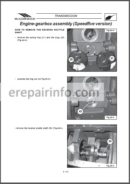
Engine-Gearbox Assembly (Speedfive Version)
Engine-Gearbox Assembly (Powershuttle Version)
Gearbox (Speedfive Version)
Gearbox (Powershuttle Version)
Wd Housing
Bevel Gear Pair And Rear Differential
Side Final Drives
Rear Brakes
Control Levers
SPECIAL TOOLS - -ENGINE-GEARBOX ASSEMBLY (SPEEDFIVE VERSION)
GUIDELINES FOR DISASSEMBLY, RE-ASSEMBLY AND ADJUSTMENTS (4WD VERSION)
Engine-Gearbox Assembly (Speedfive Version)
Drawing Of Assembly And Main Components
Description Of Operation
Guidelines For Disassembly
Guidelines For Re-Assembly And Inspection - -ENGINE-GEARBOX ASSEMBLY (POWERSHUTTLE VERSION)
GUIDELINES FOR DISASSEMBLY, RE-ASSEMBLY AND ADJUSTMENTS (4WD VERSIONS)
Engine-Gearbox Assembly (Powershuttle Version)
Drawing Of Assembly And Main Components
Description Of Operation
Drawing Of Assembly Of Powerfive Unit
Description Of Operation Of Powerfive Unit
Guidelines For Disassembly
Guidelines For Re-Assembly And Inspections
VERSION WITHOUT POWERFIVE
B7 – Drawing Of Assembly And Main Components
B8 – Description Of Operation
B9 – Guidelines For Disassembly, Re-Assembly And Adjustments - -GEARBOX (SPEEDFIVE VERSION)
GUIDELINES FOR DISASSEMBLY, RE-ASSEMBLY AND ADJUSTMENTS (4WD VERSIONS)
Gearbox (Speedfive Version)
Drawing Of Assembly And Main Components
Description Of Operation
Guidelines For Disassembly
Guidelines For Re-Assembly And Inspections - -GEARBOX (POWERSHUTTLE VERSION)
D – GEARBOX (POWERSHUTTLE VERSION)
D1 – Drawing Of Assembly And Main Components
D2 – Description Of Operation
D3 – Guidelines For Disassembly
D4 – Guidelines For Re-Assembly And Inspections - -4WD HOUSING
GUIDELINES FOR DISASSEMBLY, RE-ASSEMBLY AND ADJUSTMENTS (4WD VERSION)
4Wd Housing
Drawing Of Assembly And Description Of Operation (Version With Creeper)
Drawing Of Assembly And Description Of Operation (Version Without Creeper)
Drawing Of Assembly Of The Housing In 2Wd Tractors
Park Lock
Guidelines For Disassembly
Guidelines For Re-Assembly And Inspections - -BEVEL GEAR PAIR AND REAR DIFFERENTIAL
BEVEL GEAR PAIR AND REAR DIFFERENTIAL
Drawing Of Assembly And Main Components
Description Of Operation
Driving Torques And Sealants
Guidelines For Disassembly, Re-Assembly And Inspections
Guidelines For Adjustments - -SIDE FINAL DRIVES
GUIDELINES FOR DISASSEMBLY, RE-ASSEMBLY AND ADJUSTMENTS
Side Final Drives
Drawing Of Assembly And Main Components
Description Of Operation
Guidelines For Inspections And Adjustments
Driving Torques And Sealants - -REAR BRAKES
GUIDELINES FOR DISASSEMBLY, RE-ASSEMBLY AND ADJUSTMENTS
Rear Brakes
Drawing Of Assembly And Main Components
Description Of Operation
Guidelines For Inspections And Adjustments - -CONTROL LEVERS
GUIDELINES FOR DISASSEMBLY, RE-ASSEMBLY AND ADJUSTMENTS
Control Levers
Drawing Of Assembly And Main Components
General Description
Driving Torques And Sealants
SPECIAL TOOLS - -4WD FRONT AXLE
PRECAUTIONS AND SAFETY RECOMMENDATIONS
GENERAL DESCRIPTION
Drawing Of Assembly And Main Components
Description Of Operation
Wd Engagement (Spring-On)
Front Brakes
TECHNICAL SPECIFICATIONS
Main Technical Specifications
Driving Torques And Sealants
GUIDELINES FOR DISASSEMBLY, RE-ASSEMBLY AND ADJUSTMENTS
Guidelines For Disassembly
Guidelines For Re-Assembly, Inspections And Adjustments
SPECIAL TOOLS - -POWER TAKE-OFF
PRECAUTIONS AND SAFETY RECOMMENDATIONS
GENERAL DESCRIPTION
HYDRAULIC POWER TAKE-OFF
Drawing Of Assembly And Main Components (Only Version With Independent Pto)
Description Of Operation (Only Version With Independent Pto)
Drawing Of Assembly And Main Components (Version With Proportional Pto)
Description Of Operation (Version With Proportional Pto)
Description Of Controls
Power Train Diagrams
MECHANICAL POWER TAKE-OFF
Drawing Of Assembly And Main Components
Description Of Operation
Description Of Controls
Power Train Diagrams
TECHNICAL SPECIFICATIONS
Main Technical Specifications
Driving Torques And Sealants
GUIDELINES FOR DISASSEMBLY, RE-ASSEMBLY AND ADJUSTMENTS
HYDRAULIC POWER TAKE-OFF
Guidelines For Disassembly
Guidelines For Re-Assembly, Inspections And Adjustments
MECHANICAL POWER TAKE-OFF (SERIES F 95-105)
Guidelines For Disassembly
Guidelines For Re-Assembly, Inspections And Adjustments
MECHANICAL POWER TAKE-OFF (SERIES F 60-70-75-85)
Guidelines For Disassembly, Re-Assembly, Adjustment And Inspection
SPECIAL TOOLS - -HYDRAULIC CIRCUIT – ORCHARD TRACTORS
PRECAUTIONS AND SAFETY WARNINGS
GENERAL DESCRIPTION
General Hydraulic System (Speedfive Version)
General Hydraulic System (Powershuttle Version)
TECHNICAL SPECIFICATIONS
Main Technical Specifications
HYDRAULIC BRAKING SYSTEM
Hydraulic Braking System
Description Of The Operating Mode
Operation Of Brake Pump With Compensator
Bleeding Air From The Rear Brake Circuit
Bleeding Air From The Front Brake Circuit
Brake Adjustment
Brake Circuit Shut-Off Valve
MAIN COMPONENTS OF THE LOW PRESSURE CIRCUIT
Hydraulic Pump
Power Steering Circuit
Sx Hydraulic Power Pack (Powershuttle
Block For Forced Lubrication Valve (Powershuttle Version)
Block For Reverse Shuttle Solenoid Valves And Lubrication (Powershuttle Version)
Block For Pto Solenoid Valves And Brake Unit (Powershuttle Version)
Power Clutch Control Valve (Speedfive Version)
Hydraulic Clutches (Powershuttle Version)
Front/Rear Diff Lock Supply System (Powershuttle Version)
Rear Pto & Brake Unit Supply System (Powershuttle Vers)
4Wd Supply System (Spring-On) (Powershuttle Version)
“Powerfive” Unit Supply System (Powershuttle Version) - -HYDRAULIC CIRCUIT- VINEYARD TRACTORS
- -MECHANICAL POWER LIFT
PRECAUTIONS AND SAFETY RECOMMENDATIONS
GENERAL DESCRIPTION
Drawing Of Assembly And Main Components
Power Lift Operating Modes-
Main Components Of The Valve System
Operating Phases Of The Valve System
TECHNICAL SPECIFICATIONS
Main Technical Specifications
Driving Torques And Sealants
INSPECTIONS, ADJUSTMENTS AND TROUBLESHOOTING-
Hydraulic Tests For Valve System
Power Lift Adjustments
Operating Pressure Tests
Troubleshooting
SPECIAL TOOLS - -ELECTRONIC POWER LIFT
- -ELECTRICAL SYSTEM – ORCHARD TRACTORS
PRECAUTIONS AND SAFETY RECOMMENDATIONS
GENERAL DESCRIPTION
Basic Concepts
Electricity Symbols
How To Read And Interpret A Functional Wiring Diagram
TECHNICAL SPECIFICATIONS AND DIAGRAMS
Introduction
Cable Colour Chart
General Locations Of The Wiring
Nao Kit Cable Line
SERIES F SPEEDFIVE FOOTSTEP VERSION
TECHNICAL SPECIFICATIONS
Wiring
SERIES F POWERSHUTTLE FOOTSTEP VERSION
Technical Specifications
Wiring
MAIN COMPONENTS
INTRODUCTION
Sensors And Potentiometers
Solenoid Valves
Switches And Buttons
Instrument
Reverse Shuttle Lever (Powershuttle Version)
Electronic Control Unit (Powershuttle Version) - -ELECTRICAL SYSTEM-VINEYARD TRACTORS
- -CALIBRATION
PRECAUTIONS AND SAFETY WARNINGS
INTRODUCTION
Introduction To Calibration
Components Involved
Main Technical Specifications
CALIBRATION PROCEDURE
Safety Notes
When To Calibrate And In Which Conditions
Calibration - -TROUBLESHOOTING
PRECAUTIONS AND SAFETY WARNINGS
INTRODUCTION
Autodiagnosis And Troubleshooting
Conventional Troubleshooting
ALARM CODES
Safety Notes
Alarm Code Autodiagnosis - -SPECIAL TOOLS
01 FRI MYT
01 FRI REX
141 DS LG
143 DS LG
01 DS REX
02 DS REX
01 CMB MYT
01 CMB REX
02 CMB REX
03 CMB REX
01 DIF MYT
02 PTO MYT
01 PTO REX
02 DT MYT
01 DT REX
02 DT REX
04 DT REX
122 IDR GL
125 IDR GL
02 IDR MYT
03 IDR MYT
05 IDR MYT
01 IDR REX
02 IDR REX
03 IDR REX
05 IDR REX
CR 342
CR 347
R 504
What you get
You will receive PDF file with high-quality manual on your email immediately after the payment.



Reviews
There are no reviews yet