Factory Troubleshooting And Repair Manual For Case Cummins 9 Liter Engine. Manual Contains Illustrations, Instructions, Diagrams For Step By Step Remove And Install, Assembly And Disassembly, Service, Inspection, Repair, Troubleshooting, Tune-Ups.
Format: PDF
Language: English
Pages: 526
Number: 6-10450R0 (september 2000)
Bookmarks: Yes
Model
Case Cummins Engine
9 Liter
Contents
-INTRODUCTION
About the Manual
General Cleaning Instructions
General Repair Instructions
General Safety Instructions
How to Use the Manual
Illustrations
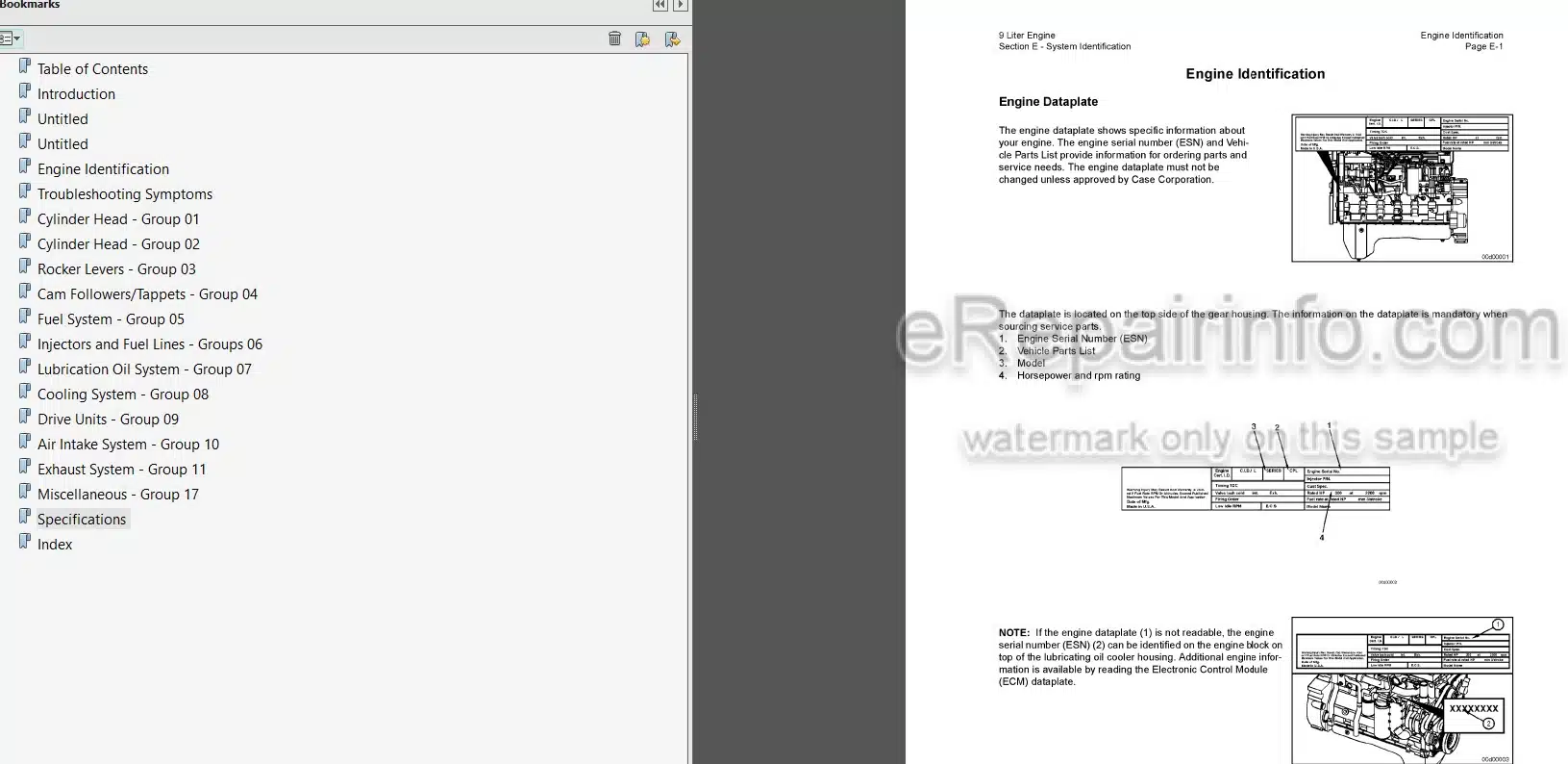
-ENGINE IDENTIFICATION
Engine Identification
Engine Views
Specifications
-TROUBLESHOOTING SYMPTOMS
Troubleshooting Procedures and Techniques
Troubleshooting Symptoms Charts
Engine Noise Diagnostic Procedures General Information
Main Bearing Noise
Connecting Rod Bearing Noise
Piston Noise
-CYLINDER HEAD
Bearings, Connecting Rod
Bearings, Main
Camshaft
Camshaft Bushings
Camshaft Gear (Camshaft Removed)
Connecting Rod
Crankshaft
Crankshaft Gear, Front (Crankshaft Installed)
Crankshaft Seal, Front
Crankshaft Seal, Rear
Crankshaft Wear Sleeve, Front
Crankshaft Wear Sleeve, Rear
Cylinder Liner
Gear Cover, Front
Gear Housing, Front
Piston
Piston and Connecting Rod Assembly
Piston Rings
Install
Service Tools
Cylinder Block
Vibration Damper, Rubber
Vibration Damper
Crosshead
Cylinder Head
Injector Protrusion
Service Tool
Valve, Cylinder Head
-ROCKER LEVERS
Crankcase Breather (Internal)
Overhead Seat
Rocker Lever
Rocker Lever Cover
-CAM FOLLOWERS/TAPPETS
Push Rods or Tubes
Tappet
-FUEL SYSTEM
Engine Fuel Heater Electric
Flow Diagram, Fuel System
Fuel Flow
Fuel Injection Pump, Rotary
Fuel Lift Pump
Fuel Pump
Fuel Pump Accumulator
Fuel Pump Accumulator Module
Fuel Pump Cam Housing
Fuel Pump Cam Housing Module
Fuel Pump Delivery Valve
Fuel Pump Distributor Inlet Fitting
Fuel Pump Distributor Module
Fuel Pump Gear Pump
Fuel Pump Gear Pump Module
Fuel Pump Injection Control Valve Module
Fuel Pump Pressure and Temperature Sensors
Fuel Pump Rate Shape Tube
Fuel Pump Timing
Fuel System – General Information
General Information
Injection Control Valve
Click Test
Pumping Control Valve
Rotor, CAPS Fuel Injection Pump
Service Tools
Fuel System
Snubber, Rate Shape
Specifications
-INJECTORS AND FUEL LINES
Air in Fuel
Fuel Connector (Head Mounted)
Fuel Drain Line Restriction
Fuel Drain Lines
Fuel Filter (Spin-On Type)
Fuel Filter Head Bracket
Inspect for Reuse
Fuel Inlet Restriction
Initial Check
Fuel Pump Air Bleed Line
Fuel Supply Lines
-LUBRICATION OIL SYSTEM
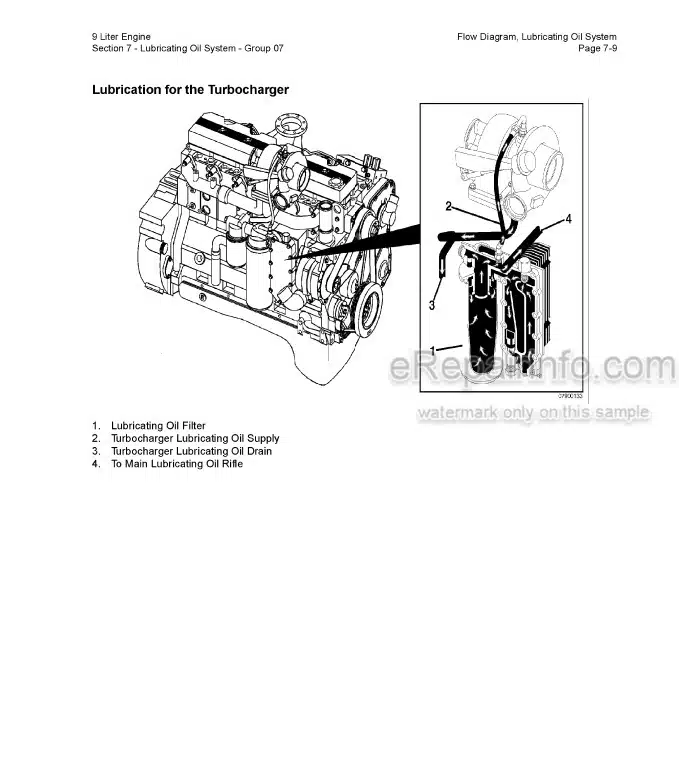
Flow Diagram, Lubricating Oil System
Engine Oil Heater
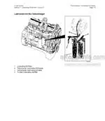
Lubricating Oil and Filters
Lubricating Oil Cooler
Leak Test
Lubricating Oil Dipstick
Lubricating Oil Dipstick Tube
Lubricating Oil Filter (Spin-On)
Lubricating Oil Pan
Lubricating Oil Pressure Regulator (Main Rifle)
Lubricating Oil Pressure Sensor
Lubricating Oil Pump
Lubricating Oil Suction Tube (Block-Mounted)
Lubricating Oil System – General Information
Lubricating Oil Thermostat
Specifications
-COOLING SYSTEM
Coolant Filter
Coolant Filter Head
Coolant Filter Valve
Coolant Heater
Cooling System
Cooling System Diagnostics
Coolant Temperature Gauge
Drive Belt, Cooling Fan
Fan, Cooling
-DRIVE UNITS
Hydraulic Pump Drive
-AIR INTAKE SYSTEM
Air Crossover
Air Inlet Connection
Air Intake Manifold
Air Intake Restriction
Air Intake System – General Information
Air Leaks, Air Intake and Exhaust Systems
Charge Air Cooler (CAC)
Cold Starting Aid
Flow Diagram, Air In take System
Air Intake System
Turbocharger
Turbocharger Axial Clearance
Turbocharger Blade Damage
Turbocharger Compressor Seal Leaks
Turbocharger Oil Drain Line
Turbocharger Oil Supply Line
Turbocharger Radial Bearing Clearance
Turbocharger Turbine Seal Leaks
Turbocharger Wastegate Valve Body
-EXHAUST SYSTEM
Exhaust Manifold, Dry
Exhaust Restriction
Flow Diagram, Exhaust System
Specifications
-MISCELLANEOUS
Cup Plug
Pipe Plug
Straight Thread Plug
-SPECIFICATIONS
Air Intake System – Specifications
Air Intake System – Torque Values
Cam Followers/Tappets
Capscrew Markings and Torque Values
Capscrew Markings and Torque Values – Metric
Capscrew Markings and Torque Values – US Customary
Cooling System – Specifications
Cooling System – Torque Values
Cylinder Block – Specifications
Cylinder Block – Torque Values
Cylinder Head – Specifications
Cylinder Head – Torque Values
Exhaust System – Specifications
Exhaust System – Torque Values
Fraction, Decimal, Millimeter Conversions
Fuel System – Specifications
Fuel System – Torque Values
Injectors and Fuel Lines – Specifications
Injectors and Fuel Lines – Torque Values
Lubricating Oil System – Specifications
Lubricating Oil System – Torque Values
Newton-Meter to Foot-Pound Conversion Chart
Pipe Plug Torque Values
Rocker Levers – Specifications
Rocker Levers – Torque Values
Tap-Drill Chart – U.S. Customary and Metric
Weights and Measures – Conversion Factors
What you get
You will receive PDF file with high-quality manual on your email immediately after the payment.



Reviews
There are no reviews yet