Factory Service Manual For Gehl Wheel Loader. Manual Contains Illustrations, Instructions, Diagrams For Step By Step Remove And Install, Assembly And Disassembly, Service, Inspection, Repair, Troubleshooting, Tune-Ups.
Format: PDF
Language: English
Pages: 134
Number: 50940188 (may 2013)
Searchable: Yes
Wiring Diagrams: Yes
Hydraulic Diagrams: Yes
Model
Gehl Wheel Loader
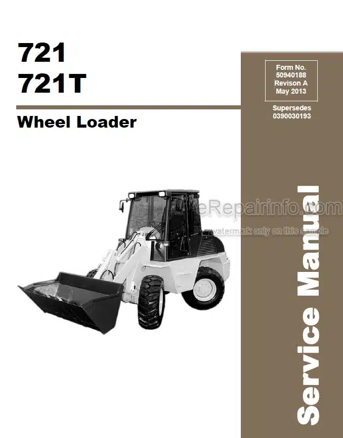
721
721T
Contents
-MAINTENANCE
Engine Fluids And Lubricants
Maintenance Kits
Maintenance Plan 621/721 (Model 303-00/304-00)
Maintenance Plan 721 Telescopic (Model 303-10)
-ENGINE
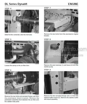
Engine: Overview
Safety
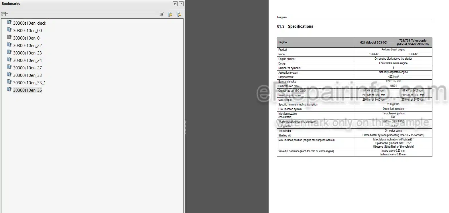
Specifications
Tightening Torques
Viton Seals
Crankcase Breather
Fuel System
Thermostat
New Gear-Driven Coolant Pump
Electrical Equipment
-POWER TRAIN
Variable Displacement Motor – Overview
Solenoid Valve – Driving Direction
Hydraulic Circuit-Drive
Adjustment Work On Drive
-AXLES
Type Label – Axle
Rear Axle Tightening Torques
Overview
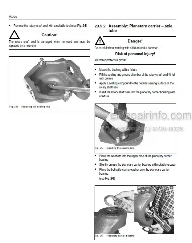
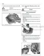
Sealing: Planetary Drive And Wheel Hub
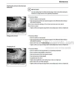
Sealing: Planetary Carrier, Axle Tube And Differential
Type Label – Gearbox
Tightening Torques Gearbox 20 kph
Tightening Torques Gearbox 40 kph (Option)
Gearbox Sealing Work
-BRAKES
Overview – Parking Brake
Brake Caliper – Adjustment
Service Brake
-STEERING
Overview – Steering Circuit
Steering Circuit
Steering Ram Front Axle/Rear Axle
Adjusting The Steering Sensors
-ELECTRICAL SYSTEM
Ohm’s Law (Current, Voltage, Resistance); Power
Measuring Equipment, Measuring Methods
Terminal Description
Cable Colour Coding
Relay
Electrical Equipment
Electronics Box
Wiring Harness Engine And Frame
Wiring Harness – Cab
Electrical Diagram (Standard Equipment) Model 303-00/304-00/303-10
Wiring Diagram – Options
-HYDRAULIC SYSTEM
Control Valve Circuit – Loader Unit Model 303-00/304-00
Hydraulic Pump – Hydraulic Oil Tank Model 303-00/304-00 Circuit
Joystick – Control Valve Model 303-00/304-00 Circuit
Control Valve – Telescopic Unit Model 303-10 Circuit
Hydraulic Pump – Hydraulic Oil Tank Circuit Model 303-10
Joystick – Control Valve Circuit Model 303-10
Hydraulics Diagram Model 303-00/304-00
Hydraulics Diagram Model 303-10
Hydraulics Diagram (Option) Model 303-00/304-00
Hydraulics Diagram (Option) Model 303-10
What you get
You will receive PDF file with high-quality manual on your email immediately after the payment.





Reviews
There are no reviews yet