Factory Workshop Manual For Deutz Fahr Tractor. Manual Contains Illustrations, Instructions, Diagrams For Step By Step Remove And Install, Assembly And Disassembly, Service, Inspection, Repair, Troubleshooting, Tune-Ups.
Format: PDF
Language: English
Pages: 696
Number: 307.1079.3.6
Bookmarks: Yes
Searchable: Yes
Wiring Diagrams: Yes
Hydraulic Diagrams: Yes
Model
Deutz Fahr Tractor
AGROTRON 106 MK3
AGROTRON 110 MK3
AGROTRON 115 MK3
AGROTRON 120 MK3
AGROTRON 135 MK3
AGROTRON 150 MK3
AGROTRON 165 MK3
Contents
INTRODUCTION
SAFETY NOTES
HOW THE MANUAL IS STRUCTURED
HOW TO CONSULT THE MANUAL
HOW TO USE AND UPDATE THE MANUAL
SAFETY PRECAUTIONS FOR REMOVAL AND REFITTING OPERATIONS
LIFTING INSTRUCTIONS
STANDARD TIGHTENING TORQUES FOR NUTS AND BOLTS
THREADLOCKERS, ADHESIVES, SEALANTS AND LUBRICANTS
SPECIAL TOOLS
CONVERSION FACTORS
-TECHNICAL DESCRIPTIONS AND INFORMATION REGARDING THE MECHANICAL AND HYDRAULIC OPERATION OF MACHINE COMPONENTS, THE DESIGNATIONS OF THE VARIOUS COMPONENTS, HYDRAULIC DIAGRAMS AND GENERAL TECHNICAL DATA.
Transmission
Braking System
Hydraulic Front Axle Suspension
Front Axle
Hydraulic System
-A GUIDE TO THE USE OF THE NECESSARY SOFTWARE FOR MACHINE AND ENGINE CONFIGURATION AND FOR DIAGNOSTIC.
Operator’s Manual Serdia (Level Iii)
Operator’s Manual EDS (Electronic Diagnosis System)
-THE METHODS, CHECKS AND ADJUSTMENTS REGARDING THE EXTERNAL COMPONENTS; THE OPERATIONS DEALT WITH IN THIS SECTION DO NOT REQUIRE REMOVAL OF THE VARIOUS ASSEMBLIES THAT FORM THE TRACTOR FRAME AND CAB.
Method For Removal And Refitting Of Rigid Pipes And Wiring
Pump Side Systems And Wiring (CC Version With Priority Valve)
Detail Of Pump Side Systems And Wiring (CC Version With Priority Valve)
Upper Systems And Wiring (CC Version With Priority Valve)
Pump Side Systems And Wiring (LS Version)
Upper Systems And Wiring (LS Version)
Systems And Supplementary Hydraulic Couplers (LS Version)
Engine Hood And Lamp Assemblies
Cab Access Steps
Battery
Air Reservoir And Battery Support (Versions With Air Trailer Braking Only)
Starter Motor
Alternator
Alternator Drivebelt
Air Compressor
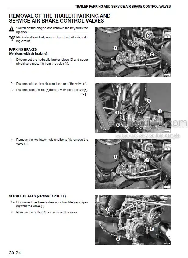
Trailer Parking And Service Air Brake Control Valves
Pressure Transducer (Version With Air Braking)
Air Pressure Regulating/Reduction Valve For Cab Lifting
Trailer Air Brakes Coupling Valve
Air Conditioning System
Compressor Drivebelt
Discharging, Flushing And Recharging The Air Conditioning System
Air Conditioning Compressor
Receiver-Drier (Models 106-150 CV)
Receiver-Drier (Model 165 CC)
Condenser Cooling Fan (Model 165 CV)
Condenser Assembly (Models 106-150 CV)
Gearbox Oil/Fuel Coolers (Models 106-150 CV)
Gearbox Oil/Fuel Coolers (Model 165 CV)
Expansion Tank
Fan (Models 106-150 CV)
Fan (Model 165 CV)
Complete Radiator/Coolers Assembly
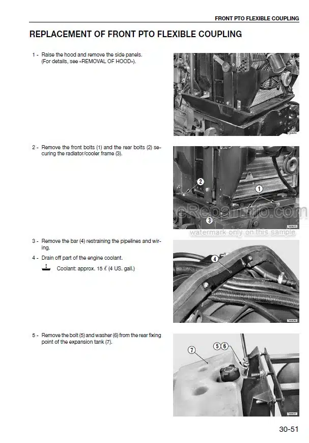
Front PTO Flexible Coupling
Turbocharger
Engine Air Inlet Pipe
Air Cleaner
Exhaust Pipe
Silencer
4Wd Propeller Shaft (Version With Front Suspension)
Brake Cylinders
Bleeding The Braking System
Brake Light Switches
Power Steering
Power Steering Unit Seals
Front Wheels
Front Fenders
Rear Wheels
Lift Valve Block
Front Lift Cylinders
Front Lift Assembly
Front PTO Assembly
Front Suspension Cylinders (Where Fitted)
Front Axle And Swinging Support (Versions With Front Suspension)
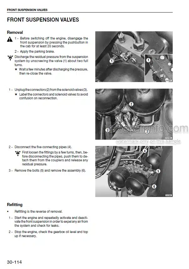
Front Suspension Solenoid Valves
Front Suspension Position Sensor
Reinforcing Side Members (For Versions With Front Lift Only)
Front Carrier (Versions With Front Suspension)
Accelerator Potentiometer
Fuel Tank
Testing The Auxiliary Services Pumps
Hydraulic Services Gear Pump (Models 106-115 CV) (CC Version)
Gear Pump Assembly ( ModeLS 120-165 CV) (CC Version)
Variable Displacement Pump (ModeLS 106-165 CV) (LS Version)
Power Steering Pump (ModeLS 106-115 CV) (CC Version)
Priority Valve (Models 106 – 115 CV)
Priority Valve (Modd. 120-165 CV)(Versions With Variable Displacement Pump)
Creeper Engagement Lever
Control Valve Assemblies (CC Version)
Control Valve Assemblies (LS Version)
Auxiliary Control Valve Assemblies
Lift Cylinders
Lift Position Sensor
Lift Draft Sensor
Driver’S Seat
Steering Wheel, Steering Column Switch Unit And Instrument Panel
Steering Column Switch Unit And The Shuttle Control Lever
Centre Console And Shroud
Right-Hand Console
Left-Hand Console
Lift, Front Suspension And Transmission Electronic Control Units
Fuse And Relay Board
Engine ECU
Clutch Pedal And Related Devices (Power Shift Version)
Clutch Pedal And Related Devices (Power Shuttle Version)
Control Panels And Levers Of The Auxiliary Service Valves And The PTO
PTO Engagement And Selection Control Cables
Auxiliary Service Valve Control Cables
Refitting The Auxiliary Service Valve Control Cables
Adjustment Of The Parking Brake Switch
Climate Control Panel
Renewal Of The Heater Valve
Cab Heater Matrix
Air Conditioning Evaporator
Right-Hand Air Conditioning Fan
Left-Hand Air Conditioning Fan
Adjustment Of The Parking Brakes
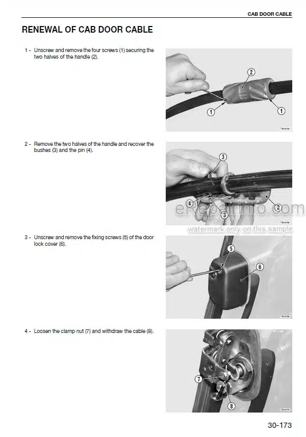
Renewal Of Cab Door Cable
Trailer Braking Air Pressure Gauge
Removal And Refitting
Powershift – Powershuttle Status Display
Cab
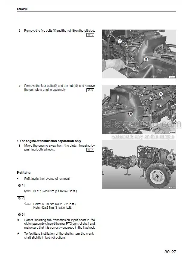
Engine -Transmission
-INFORMATION AND DIAGRAMS REGARDING THE MACHINE’S ELECTRICAL AND ELECTRONIC SYSTEMS.
The Structure Of The Unit
How To Consult The Unit
Introduction
Indices
Components
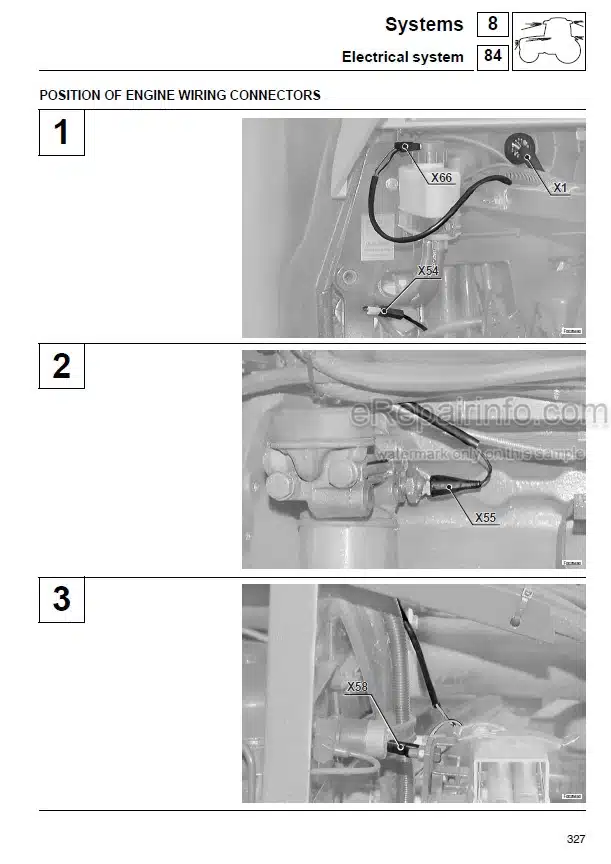
Systems
Planimetry, Wiring Diagram And Connectors Location
What you get
You will receive PDF file with high-quality manual on your email immediately after the payment.


Reviews
There are no reviews yet