


Factory Field Assembly Manual For Komatsu Hydraulic Excavator.
Format: PDF
Language: English
Pages: 219
Number: SEAW021TA102
Bookmarks: Yes
Model
Komatsu Hydraulic Excavator
PC1600-1
SN 10001 and up
Contents
-GENERAL
Points Regarding Local Assembly
Precautions When Assembling, Tightening Torque Of Bolts, Screws And Taper Seal Holes
Separate Units (Transportation Kits)
Lift Of Parts Sent Individually
Assembly Procedure, Assembly Equipment, And Schedule
Kit Layout Diagram
Tools And Equipment To Be Used
-ASSEMBLY OF CHASSIS
Assembly Of Track Frame And Axle
Travel Motor Piping
Idler Cushion Cylinder Piping
Installation Of Travel Motor Guard
Filling Swing Circle With Grease
Assembly Of Revolving Frame Assembly And Axle Assembly
Swivel Travel Piping
Swing Circle Grease Tube Piping
Installation Of Left And Right Ladders
Installation Of Left Catwalk
Installation Of Right Catwalk
Installation Of Catwalk, Handrail Beside Operator’s Cab
Installation Of Operator’s Cab Ladder
Installation Of Operator’s Cab Handrail
Installation Of Operator’s Cab Ladder, Handrail
Installation Of Handrail At Rear Of Operator’s Cab
Installation Of Handrail For Step At Rear Of Operator’s Cab
Operator’s Cab Front Frame, Handrail
Left Deck Handrail
Right Deck Handrail
Installation Of Ladder On Top Of Hydraulic Tank
Installation Of Counterweight
Installation Of Counterweight Ladders
Installation Of Handrail On Top Of Fuel Tank, Counterweight
Installation Of Fuel Tank Vibration Stopper Bracket
Installation Of Grease Reel, Hose, Bracket
Installation Of Left Cab Base Assembly
Installation Of Operator’s Cab Assembly
Installation Of Wiper Motor Cover Inside Operator’s Cab
Installation Of Operator’s Cab Assembly
Connection Of Hydraulic Piping Of Operator’s Cab Assembly
Connection Of Wiring Of Left Cab Base Assembly
Connection Of Wiring Of Operator’s Cab Assembly
Connection Of Window Washer Hose Of Operator’s Cab Assembly
Connection Of Air Piping Of Left Cab Base Assembly
Connection Of Grease Piping Of Operator’s Cab Assembly
Connection Of Air Conditioner Piping Of Left Cab Base Assembly
Connection Of Air Conditioner Piping Of Operator’s Cab Assembly
Installation Of Counterweight Lamp (Option)
Start Engine
Final Tightening Of Swing Circle Mounting Bolts
-INSTALLATION OF BACKHOE
Installation Of Boom Cylinder To Chassis
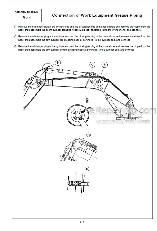
Installation Of Boom Cylinder Piping
Bleeding Air From Boom Cylinder
Boom Sub-Assembly
Installation Of Boom Assembly
Installation Of Boom Cylinder Top Pin
Connection Of Arm Assembly To Boom
Installation Of Hose Between Boom And Chassis
Installation Of Arm Cylinder Top Pin
Bleeding Air From Arm Cylinder
Installation Of Hydraulic Hoses Between Boom And Arm
Connection Of Grease Piping Between Boom And Chassis
Connection Of Wiring Between Boom And Chassis
Installation Of Hoses Between Boom And Chassis
Installation Of Hydraulic Hose, Clamps Between Boom And Chassis
Connection Of Bucket Assembly To Arm
Installation Of Bucket Link
Bleeding Air From Bucket Cylinder
-INSTALLATION OF LOADING SHOVEL
Installation Of Boom Cylinder To Chassis
Installation Of Boom Cylinder Piping
Bleeding Air From Boom Cylinder
Boom Sub-Assembly
Installation Of Boom Assembly
Installation Of Bucket Cylinder Foot Portion
Arm Sub-Assembly
Installation Of Arm Assembly
Installation Of Arm Cylinder Top Pin
Bleeding Air From Arm Cylinder
Installation Of Side Link
Installation Of Hose Between Boom And Chassis
Installation Of Hydraulic Hose Between Boom And Arm
Installation Of Front Link
Connection Of Bucket Assembly To Arm
Bleeding Air From Bucket Cylinder
Connection Of Bottom Cylinder Hose
Bleeding Air From Bottom Cylinder
Connection Of Grease Hose Between Boom And Arm
Connection Of Grease Hose At The Arm Cylinder Top
Connection Of Grease Hose At The Arm Cylinder Foot
Connection Of Grease Piping Between Boom And Chassis
Connection Of Wiring Between Boom And Chassis
Installation Of Arm Potentiometer
Adjustment Of Work Equipment Potentiometer
Adjustment Of Work Equipment Control Box (Loading Shovel)
-CHECK OF ALL PARTS DURING AND AFTER ASSEMBLY
Check Of All Parts During And After Assembly With Field Assembly Inspection Report
Flush The Hydraulic Circuit As Follows
What you get
You will receive PDF file with high-quality manual on your email immediately after the payment.


Reviews
There are no reviews yet