Factory Technical Repair And Diagnostic Manual For John Deere Compact Utility Tractor. Manual Contains Illustrations, Instructions, Diagrams For Systems Diagnosis, Theory Of Operation, Performance Testing, Tests And Adjustments, Operational Check, Unit Locations, Diagnostic Codes, Schematics And A Lot Of Other Useful Information For Service And Repair Remove And Install, Assembly And Disassembly, Inspection, Troubleshooting, Tune-Ups.
Format: PDF
Language: English
Pages: 1020
Number: TM1470 (march 1999)
Searchable: Yes
Wiring Diagrams: Yes
Hydraulic Diagrams: Yes
Model
John Deere Compact Utility Tractor
670
770
790
870
970
1070
Contents
—GENERAL INFORMATION
Safety
General Specifications
Repair Specifications
Fuel and Lubricants
Serial Number Locations
-ENGINE REPAIR
670/770
870/970/1070
790
Cooling System
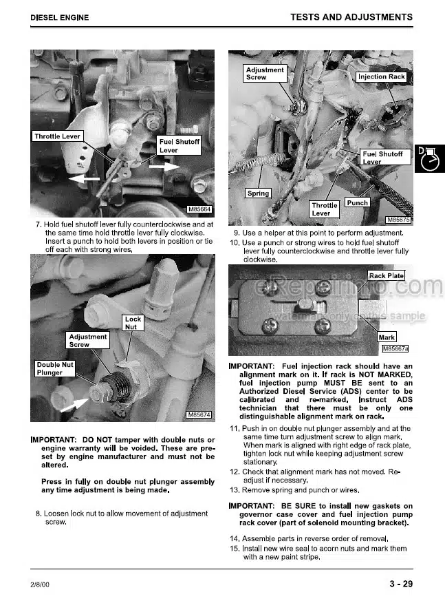
Throttle and Governor Control Linkage
Fuel System
—ELECTRICAL SYSTEM
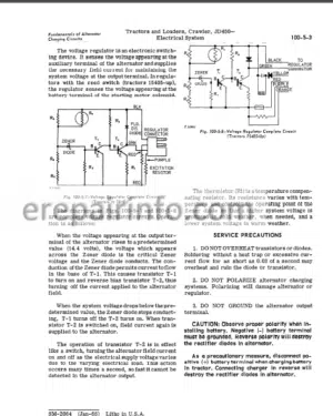
Alternator
Starter
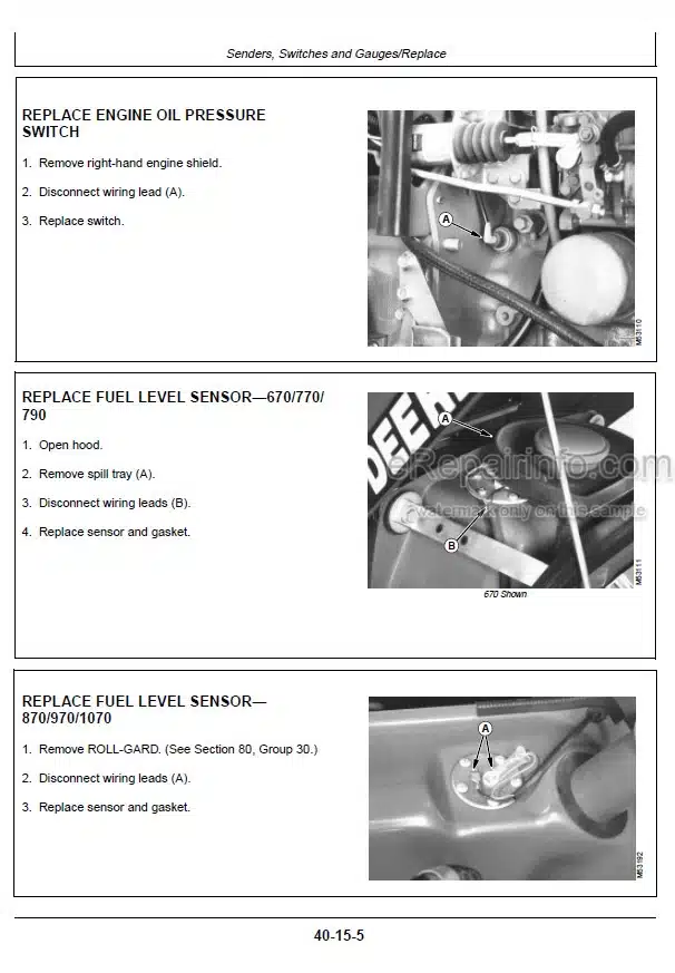
Sender, Switches and Gauges
—POWER TRAIN REPAIR—670/770/790
Clutch Housing
Single Stage Clutch
Dual Stage Clutch
Transmission
Rear PTO Drive Shaft
Differential
Final Drive
Mechanical Front Wheel Drive
Throttle and Governor Control Linkage
—POWER TRAIN REPAIR—870/970/1070
Clutch Housing
Dual Stage Clutch
Transmission
Rear PTO Drive Shaft
Differential
Final Drive
Mechanical Front Wheel Drive—870
Mechanical Front Wheel Drive—970/1070
Mid Mount PTO
—STEERING AND BRAKE REPAIR
Manual Steering
Power Steering
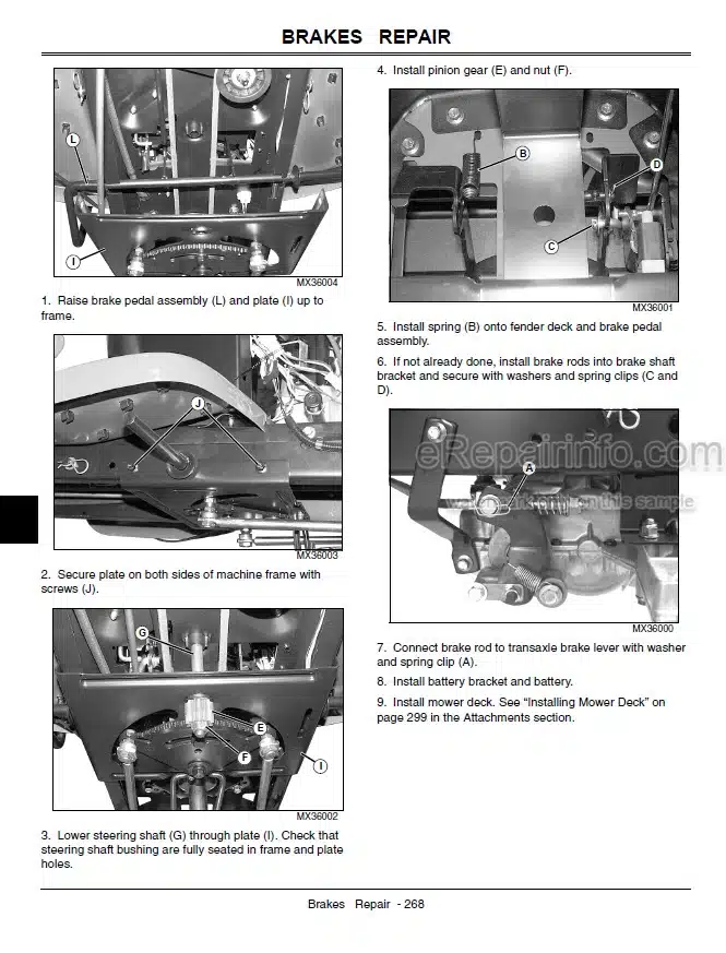
Brake Repair—670/770/790
Brake Repair—870/970/1070
—HYDRAULIC REPAIR
Hydraulic Pump and Filter
Rockshaft—670/770/790
Rockshaft—870/970/1070
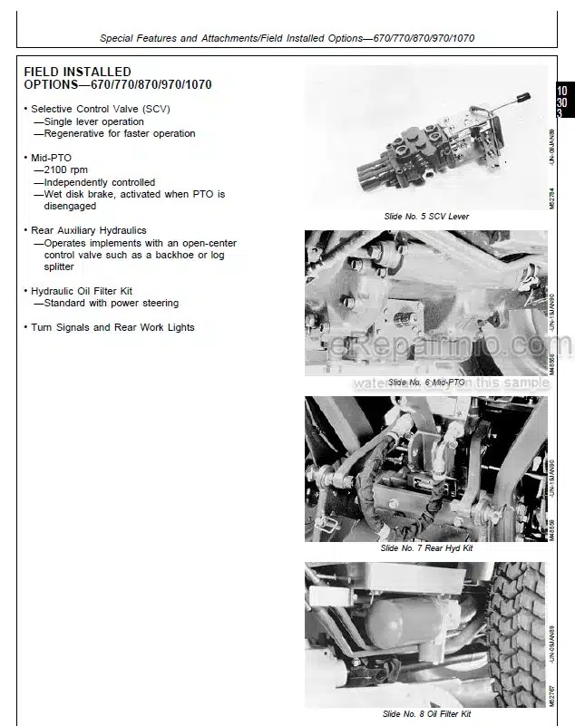
Selective Control Valve
Rear Auxiliary Hydraulic Lines
—MISCELLANEOUS REPAIR
Wheels
Front Axle
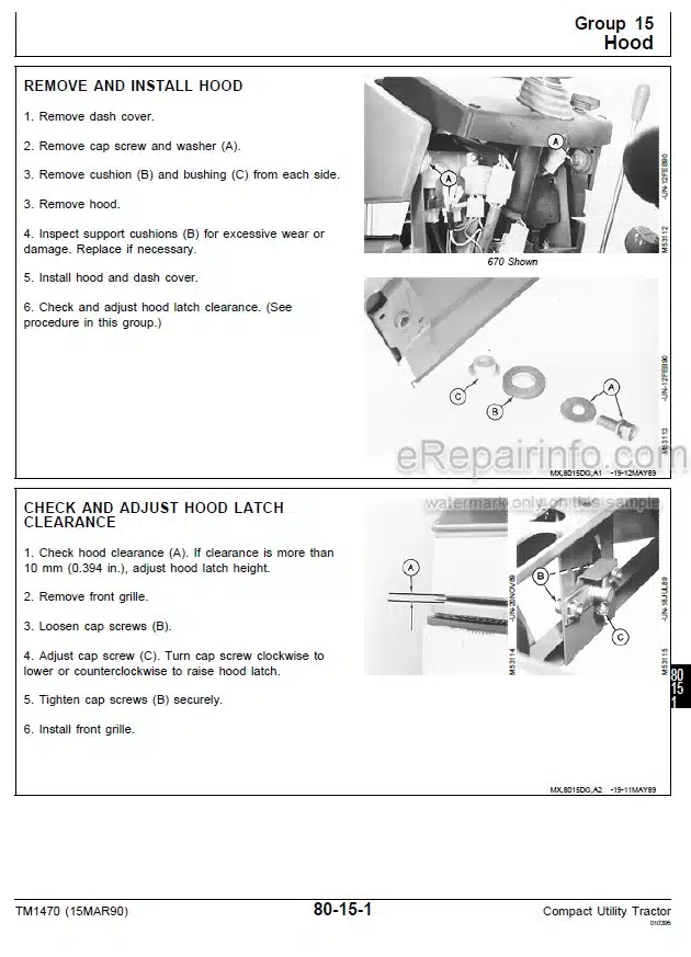
Hood
3-Point Hitch
Seat and Support
Roll-Gard
Mower Spindles
Mower Gearbox
—OPERATIONAL CHECKOUT PROCEDURE AND SPECIFICATIONS
Test and Adjustment Specifications
Operational Checkout Procedures
—ENGINE OPERATION, TESTS, AND ADJUSTMENTS
Component Locations
Theory of Operation
Engine System Diagnosis
—ELECTRICAL SYSTEM OPERATION AND TESTS
Component Location
Theory of Operation
Diagnosis and Test
Schematic
—POWER TRAIN—670/770/790
Component Location
Theory of Operation
Diagnosis and Test
—POWER TRAIN—870/970/1070
Component Location
Theory of Operation
Diagnosis and Test
—STEERING AND BRAKES
Component Location
Theory of Operation
Diagnosis and Test
—HYDRAULIC SYSTEM
Component Location
Theory of Operation
Diagnosis and Test
Schematic
What you get
You will receive PDF file with high-quality manual on your email immediately after the payment.


Reviews
There are no reviews yet