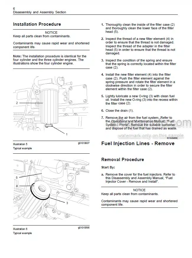
Factory Repair Manual For Manitou Telescopic Handler. Manual Contains Illustrations, Instructions, Diagrams For Step By Step Remove And Install, Assembly And Disassembly, Service, Inspection, Repair, Troubleshooting, Tune-Ups.
Format: PDF
Language: English
Pages: 1348
Issue: january 2005
Searchable: Yes
Wiring Diagrams: Yes
Hydraulic Diagrams: Yes
Model
Manitou Telescopic Handler
MT732 Serie B-E2
MT932 Serie B-E2
MLT630 Turbo Serie B-E2
MLT630-120 LSU Serie B-E2
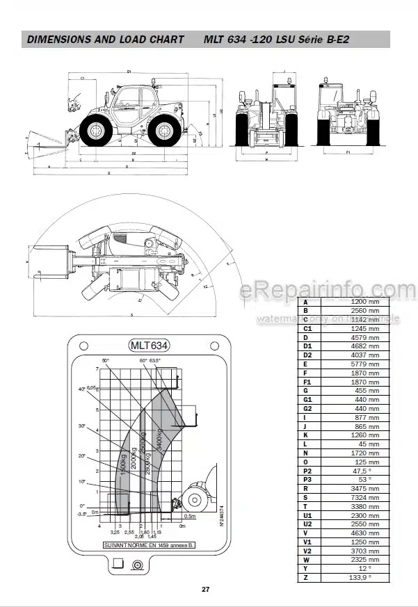
MLT634 Turbo LSU Serie B-E2
MLT634-120 LSU Serie B-E2
MLT634-120 LSU Powershift Serie B-E2
MLT731 Turbo Serie B-E2
MLT731 Turbo LSU Serie B-E2
MLT741-120 LSU Serie 2-E2
MLT741 120 LSU POWERSHIFT Serie 2-E2
MLT742 Turbo Serie 2-E2
MT1030 S Serie 2-E2
Contents
-GENERAL POINTS
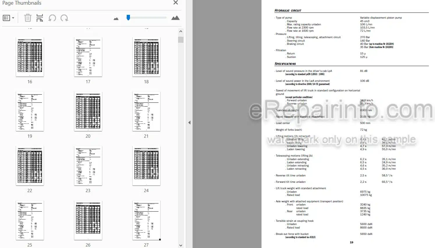
Lift Truck Characteristics
-I.C. ENGINE
The I.C. Engine Characteristics
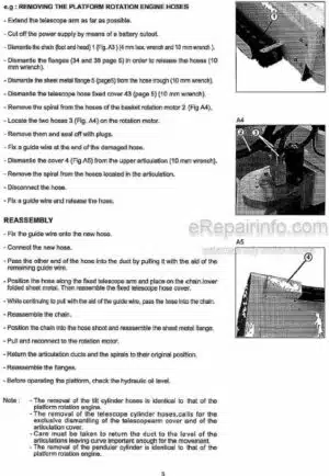
Disassembly Of The I.C. Engine
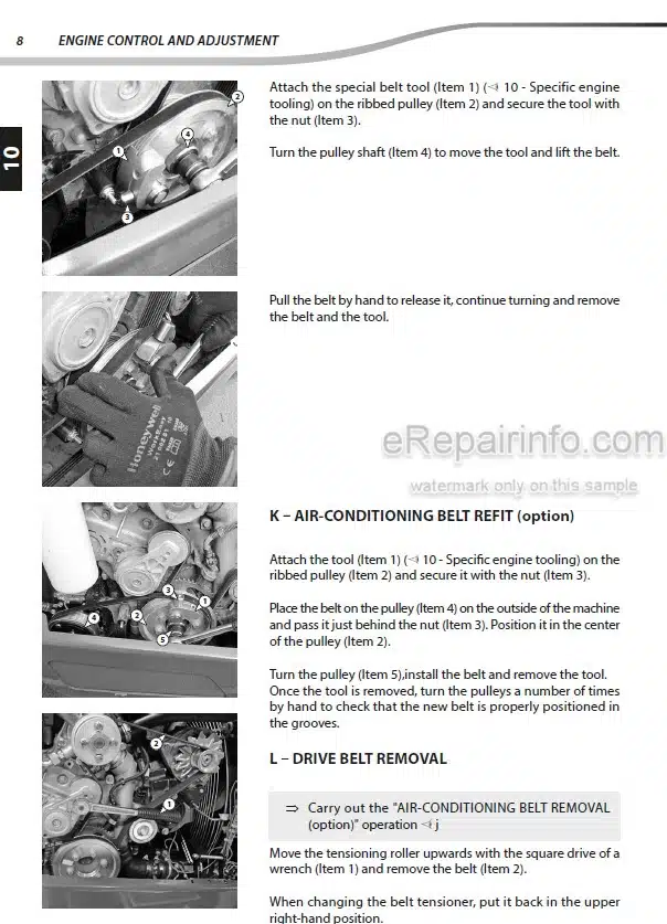
Operating And Setting Of The I.C. Engine
-CARBURATION
Fuel Sender Assembly
-ENGINE COOLING SYSTEM
Fan Belt Adjustment
-GEAR BOX – CONVERTER
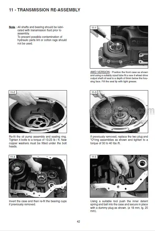
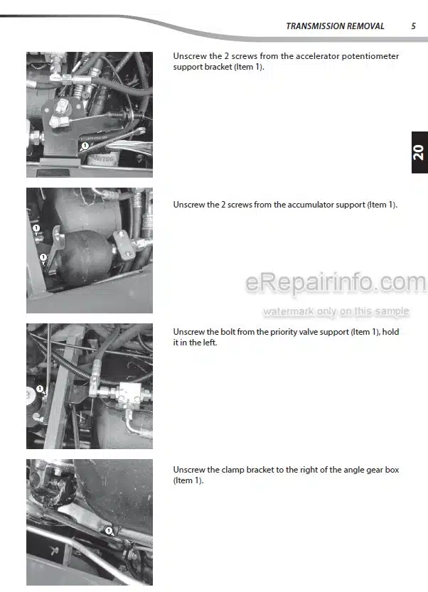
Removal Of The Transmission
Gear Box Disassembly
Reassembly
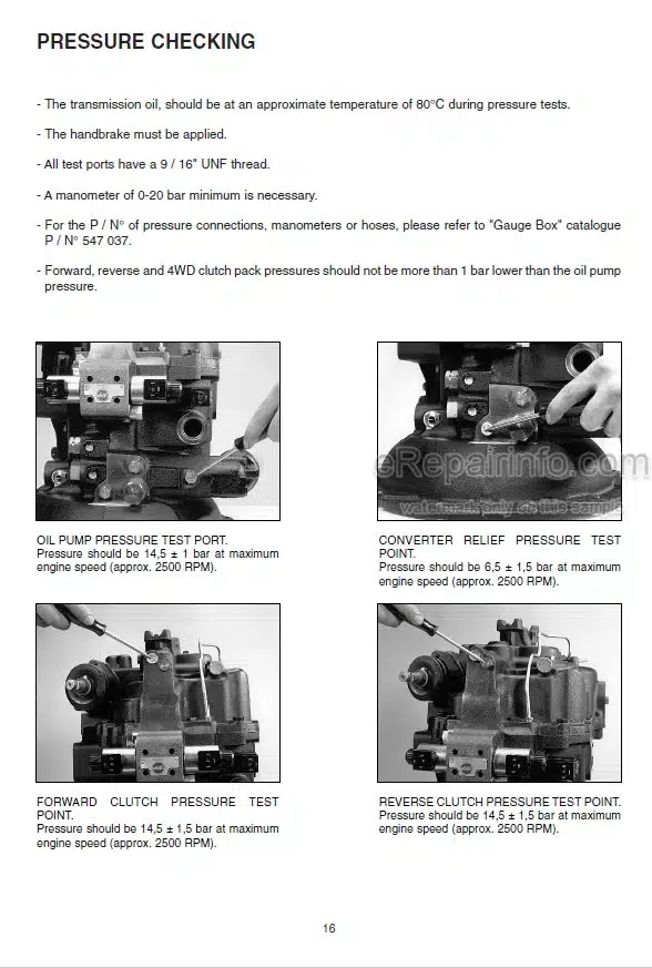
Test Procedure
Bevel Gear Disassembly
-AXLE ASSEMBLY
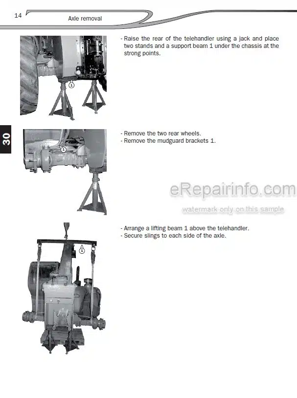
Removal Of The Front And Rear Axle Assembly
Disassembly Of The Axle Assembly
-BRAKE
Disassembly Of The Parking Brake
Bleeding The Brake Circuit
Bleeding The Trailer Brake Circuit (Option)
Hydraulic Braking Circuit
Operation Of The Brake System
-JIB
Removal Of The Jib
Jib Dismantling
Disassembly Of The Jib
-HYDRAULIC
Distributor Disassembly
Dismantling The Main Hydraulic Pump
Cylinder Disassembly
Taking Of Pressure
Hydraulic Diagram
Functioning : Electro-Hydraulic Control “EMS”
-ELECTRICITY
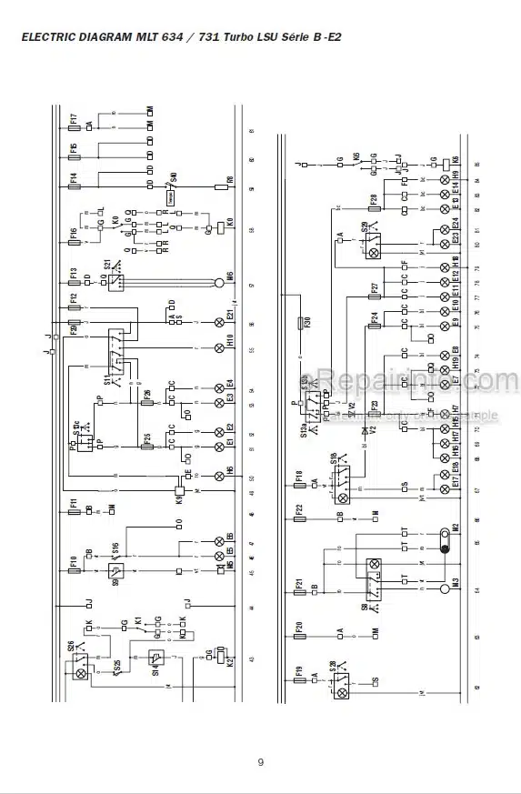
Electric Diagram
Plate Electric Diagram
Electric Circuits
Verification Of The Joystick
Operation: Progressivity Module
Operation : Power Regulation
Forced Operation Functioning
Operation Of Arm Suspension “CRC”
Operating And Setting Of The Longitudinal Stability Alarm
-AIR CONDITIONING
Air-Conditioning Operation And Adjustment
What you get
You will receive PDF file with high-quality manual on your email immediately after the payment.
Reviews
There are no reviews yet