Factory Service Manual Addendum For Gehl And Mustang Skid Steer Loader. Manual Contains Illustrations, Instructions, Diagrams For Step By Step Remove And Install, Assembly And Disassembly, Service, Inspection, Repair, Troubleshooting, Tune-Ups.
Format: PDF
Language: English
Pages: 145
Issued: may 2009
Searchable: Yes
Wiring Diagrams: Yes
Model
Mustang Skid Steer Loader with Tier3 Yanmar Engine
2066
2076
2086
Gehl Skid Steer Loader with Tier3 Yanmar Engine
5640E
6640E
Contents
-SPECIFICATIONS
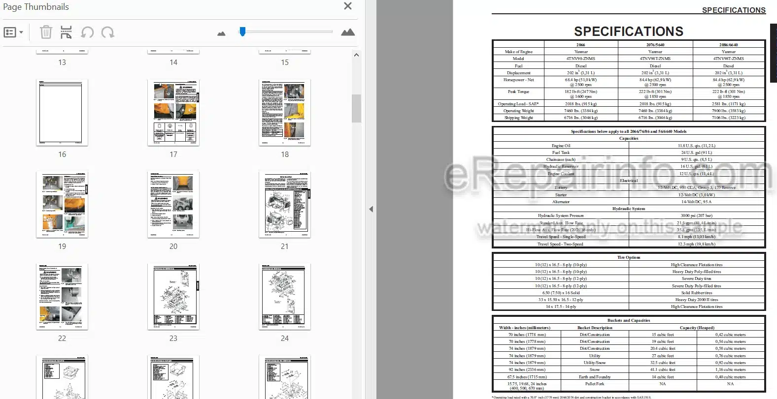
Specifications
Tire Options
Buckets and Capacities
Dimensional Specifications
-SAFETY
General Information
Signal Words
Additional Safety Reminders
Mandatory Safety Shutdown Procedure
Liftarm Support Device
Liftarm Support Device Engagement
Liftarm Support Device Disengagement
ROPS, Raising
ROPS, Lowering
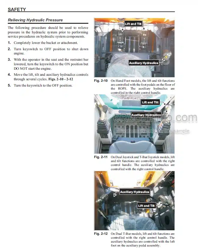
Relieving Hydraulic Pressure
Loader Lowering Procedure
Loader Raising Procedure
-LUBRICATION
General Information
Crankcase Oil
Hydraulic Oil Reservoir
Chaincases
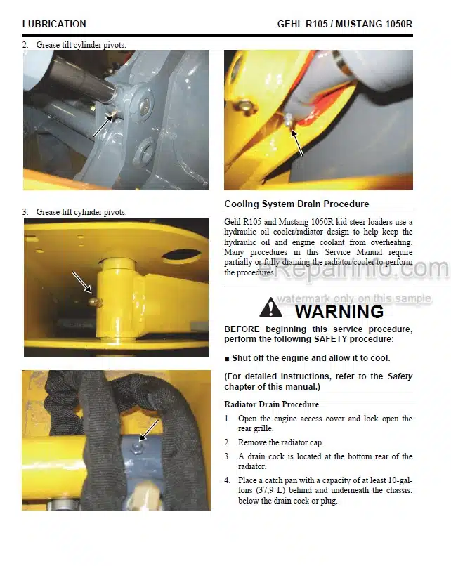
Cooling System Drain Procedures
Grease Fitting Locations
-MAINFRAME
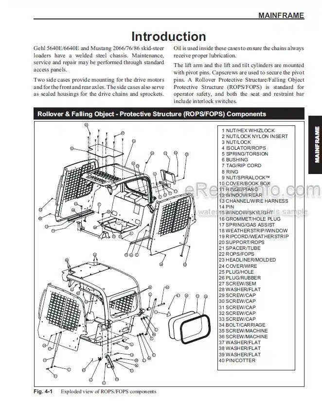
Introduction
Rollover and Falling Object – Protective Structure Components
Engine Access Cover
Chassis Components
Control Cover Components – Hand and Foot
Control Cover Components – Dual Joystick
Control Cover Components – T-Bar
Control Cover Components – T-Bar/Joystick
ROPS Removal and Installation
All-Tach Hitch Components
Control Cover, Floor Cover Removal and Installation
Crossmember Removal and Installation
Rear Grille Latch Removal and Installation
Rear Grille Removal and Installation
Rear Grille and Engine Cover Components
-CONTROLS
Introduction
Lift and Tilt Components – Hand/Foot Control Models
Lift and Tilt Components – Dual Joystick and T-Bar/Joystick Control Models
Lift and Tilt Components – T-Bar Control Models
Drive Control Components – Hand/Foot Models
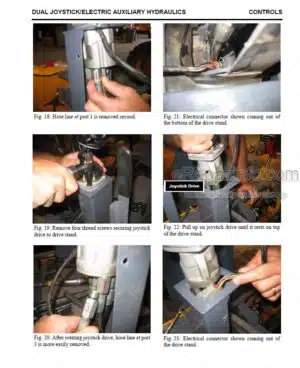
Drive Control Components – Dual Joystick Models
Drive Control Components – T-Bar and T-Bar/Joystick Models
Lift/Tilt Control Removal and Installation
Electrical Hand Throttle Removal and Installation
Electrical Foot Throttle Removal and Installation – Dual Joystick Controls
Electrical Foot Throttle Assembly – T-Bar, T-Bar/Joystick and Dual Joystick Controls
-HYDROSTATIC SYSTEM
Introduction
Single-Spccd Components – Dual Joystick Controls
Single-Speed Components – Hand/Foot Controls
2066/76 Two-Speed Components – Dual Joystick Controls
Two-Speed Components – Hand/Foot Controls
Troubleshooting Guide
Hydraulic/Hydrostatic Schematic – Dual Joystick Controls
Hydraulic/Hydrostatic Schematic – Hand/Foot Controls
-HYDRAULIC SYSTEM
Introduction
Troubleshooting Guide
Standard Auxiliary Hydraulics – Dual Joystick, H/F and T-Bar/Joystick Controls
Standard Auxiliary Hydraulics – T-Bar Controls
High-Flow Auxiliary Hydraulics – Dual Joystick, H/F and T-Bar/Joystick Controls
High-FTow Auxiliary Hydraulics – T-Bar Controls
Lift Arm Hydraulics Components – 2066/76
Lift Arm Hydraulics Components – 2086
Lift Arm Hydraulics Components – 56/6640
High-Flow Lift Arm Hydraulics Option – Dual Joystick, Hand/Foot, T-Bar/Joystick
Pressure Tests, Standard-Flow and High-Flow Auxiliary
Hydraulic Oil Filter Element Replacement
Control Valve Removal and Installation
Manifold Valve Removal and Installation
Control Valve Disassembly and Assembly
Main Relief Valve Removal and Installation
Control Valve Components – Standard-Flow and High-Flow
-ELECTRICAL SYSTEM
Introduction
Description of Operation – Right and Left Instrument Panels
Troubleshooting Guide
Chassis Electrical Components
ROPS Electrical Components
Engine Electrical Components – 2066/76/86
High-Flow and Two-Speed Electrical Components
Power Distribution Panel Test and Operation
Fuse Box Panel Test and Operation
Interlock Control Module Test
Interlock Control Module Truth Table
Two-Speed, Ride Control and Float Module Test
Two-Speed, Ride Control and Float Module Truth Table
Electrical Standard Auxiliary Hydraulic Flow System Test and Operation
Electrical High-Flow Auxiliary Hydraulic Flow System Test and Operation
Engine Throttle Test and Operation
Pilot Oil Solenoid Valve Test and Operation – Dual Joystick and Hand/Foot
Solenoid Lock Valves Test and Operation – T-Bar Only
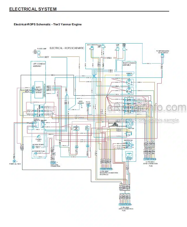
Electrical Schematics – ROPS, Chassis, Engine
-ENGINE
Introduction
Troubleshooting Guide
Engine Components – Yanmar 4TNV98 – 2066/76/86
Air Cleaner and Exhaust Components – 2066
Air Cleaner and Exhaust Components – 56/6640 and 2076/86
Radiator Cooler Components – 2066/76/86
Radiator Cooler Components – 56/6640
Remote Oil Filter Element Removal and Installation
Air Cleaner Assembly Removal and Installation
Battery and Battery Tray Removal and Installation
Starter Removal and Installation
Exhaust Assembly Removal and Installation
Fan Belt Adjustment
Radiator Cooler Removal and Installation
Fan Shroud and Cooler Mount Plates Removal and Installation
Engine Removal and Installation
Engine Diagnostic Charts
What you get
You will receive PDF file with high-quality manual on your email immediately after the payment.
Reviews
There are no reviews yet