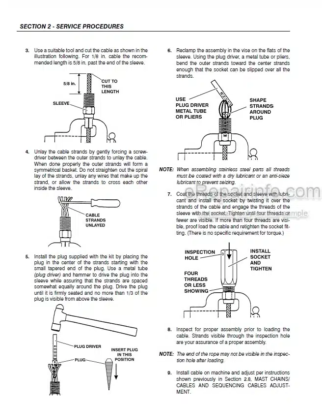
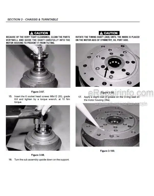
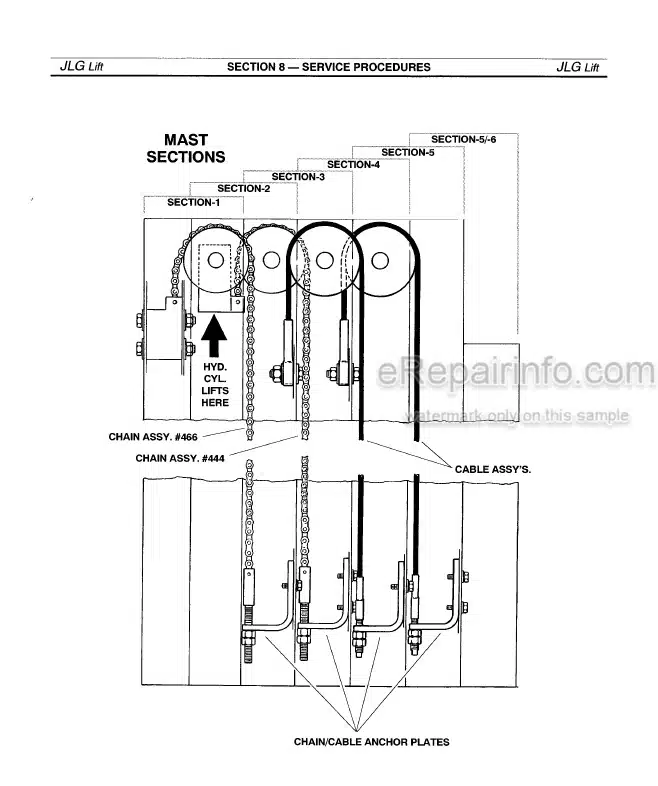
Factory Service Manual For JLG Telehandler. Manual Contains Illustrations, Instructions, Diagrams For Step By Step Remove And Install, Assembly And Disassembly, Service, Inspection, Repair, Troubleshooting, Tune-Ups.
Format: PDF
Language: English
Pages: 244
Issue: august 2012
Bookmarks: Yes
Searchable: Yes
Wiring Diagrams: Yes
Hydraulic Diagrams: Yes
Model
JLG Telehandler
G6-42A
G9-43A
G10-43A
Contents
-SAFETY PRACTICES
Introduction
Disclaimer
Operation & Safety Manual
Do Not Operate Tags
Safety Information
Safety Instructions
Safety Decals
-GENERAL INFORMATION AND SPECIFICATIONS
Replacement Parts and Warranty Information
Torque Charts
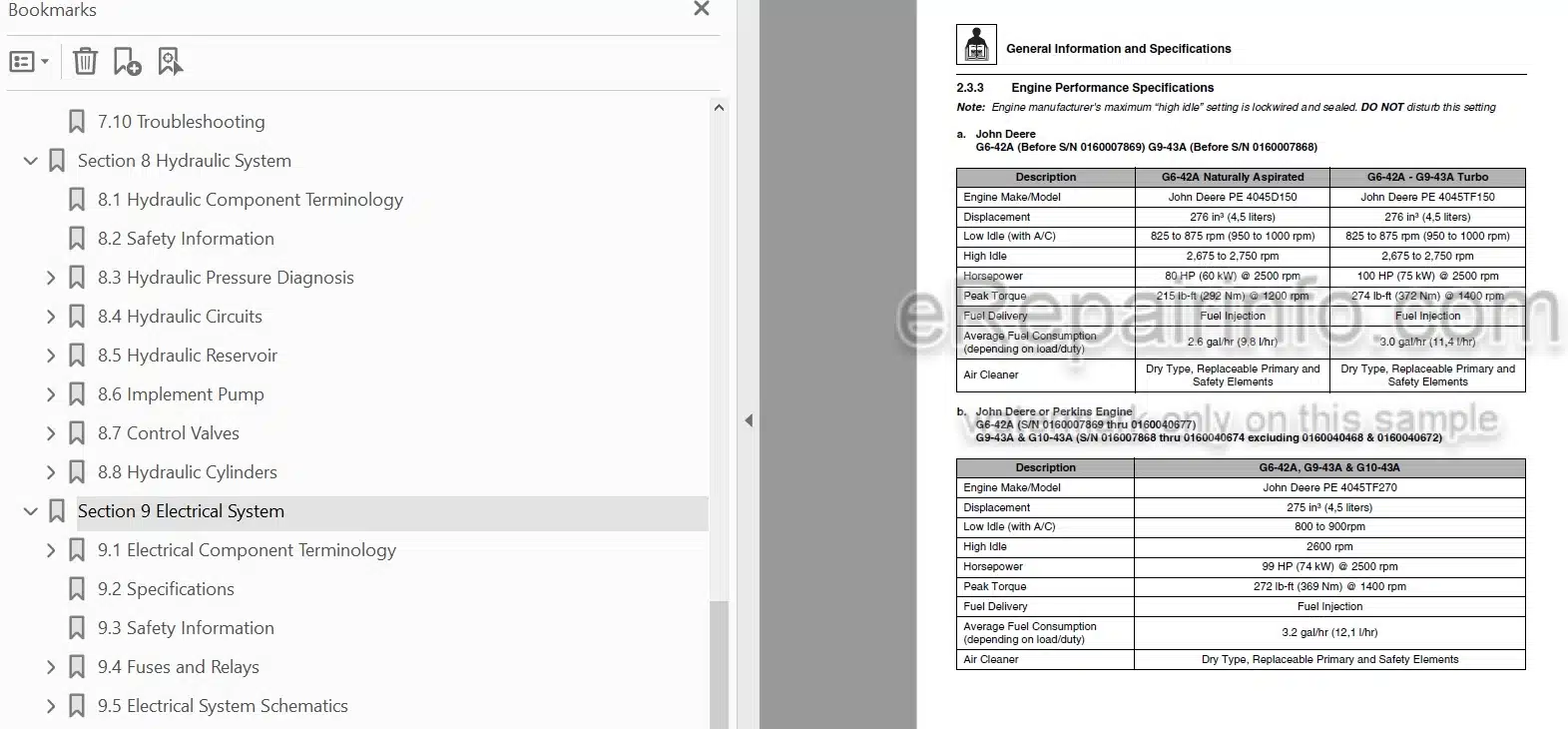
Specifications
Fluid and Lubricant Capacities
Service and Maintenance Schedule
Lubrication Schedule
-BOOM
Boom System Component Terminology
Boom System – Three Section
Boom Assembly Maintenance
Complete Boom Removal/ Installation
Boom Section Removal/ Installation
Extend/Retract Chain Removal/Installation
Push Beam – Extend/Retract Cylinder Removal/ Installation
Boom Adjustments
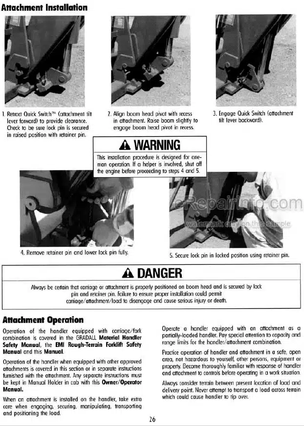
Quick Switch Assembly
Boom Head – Mounted Winch
Boom Wear Pads
Boom Extend and Retract Chains
Forks
Troubleshooting
Push Beam Temporary Brackets
-CAB AND COVERS
Operator Cab and Covers Component Terminology
Operator Cab
Cab Components
Cab Removal
Cab InstallationOperator Cab and Covers Component Terminology
Operator Cab
Cab Components
Cab Removal
Cab Installation
-AXLES, DRIVE SHAFTS, WHEELS AND TIRES
Axle, Drive Shaft and Wheel Component Terminology
General Information
Axle Assemblies
Drive Shafts
Wheels and Tires
Brakes
Towing a Disabled Machine
-TRANSMISSION
Transmission Assembly Component Terminology
Transmission Serial Number
Transmission Specifications and Maintenance Information
Transmission Replacement
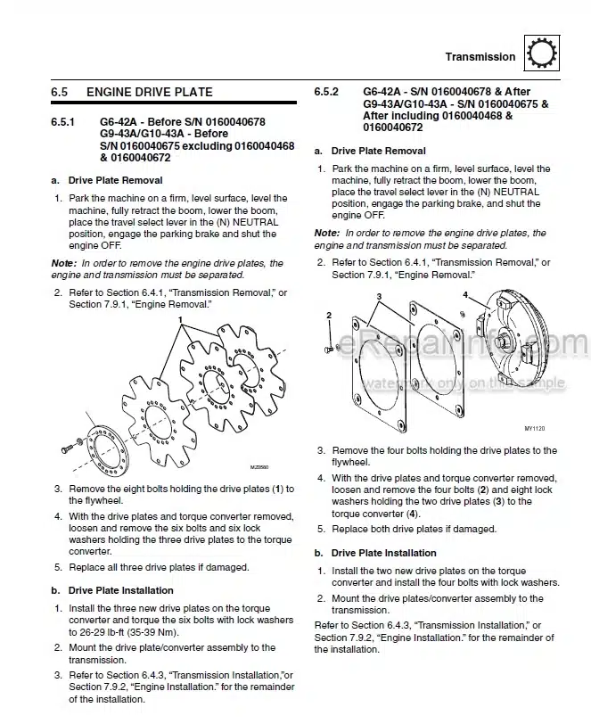
Engine Drive Plate
Transmission Cooler Thermal Bypass Valve
Troubleshooting
-ENGINE
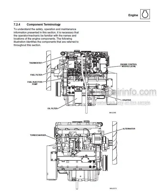
Introduction – John Deere
Introduction – Perkins
Introduction – Cummins
Engine Cooling System
Engine Electrical System
Fuel System
Engine Exhaust System
Air Cleaner Assembly
Engine Replacement
Troubleshooting
-HYDRAULIC SYSTEM
Hydraulic Component Terminology
Safety Information
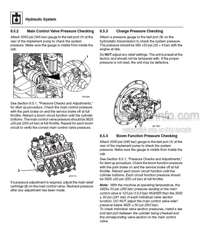
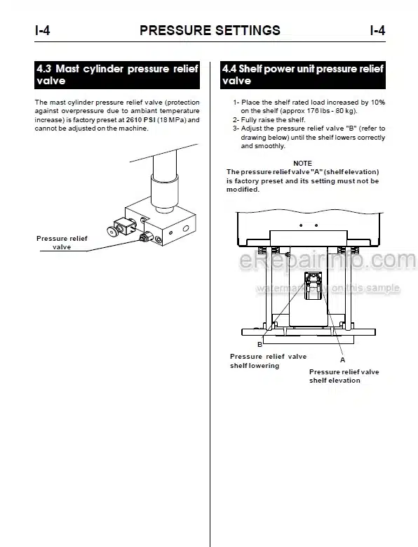
Hydraulic Pressure Diagnosis
Hydraulic Circuits
Hydraulic Reservoir
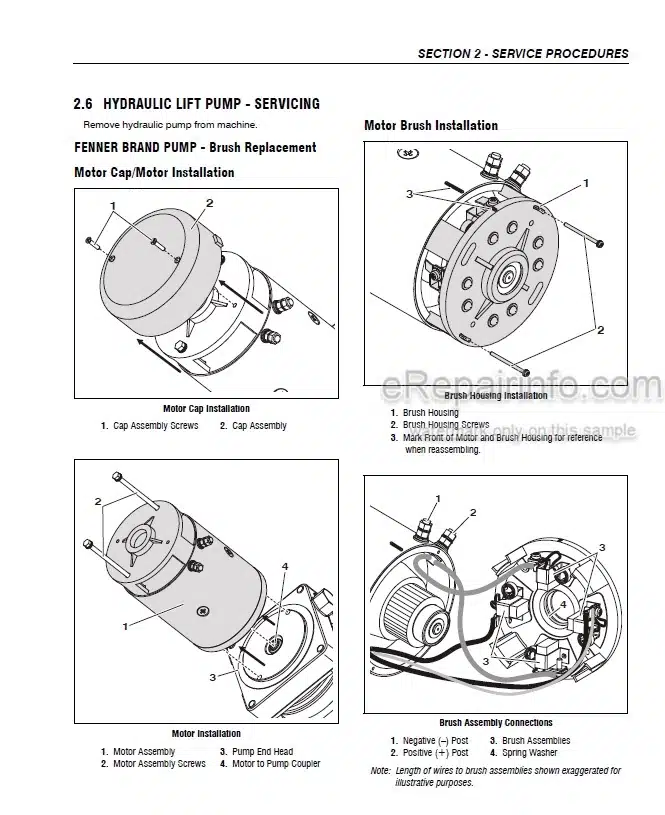
Implement Pump
Control Valves
Hydraulic Cylinders
-ELECTRICAL SYSTEM
Electrical Component Terminology
Specifications
Safety Information
Fuses and Relays
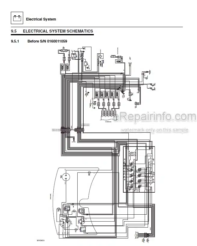
Electrical System Schematics
Circuit Breakdowns
Engine Start Circuit
Charging Circuit
Window Wiper/Washer Windshield Wiper Motor
Cab Heater and Fan
Solenoids and Senders
Display Monitor and Gauges
Dash Switches
Variable Displacement Pump Control
Hand Held Analyzer
Joystick Fault Codes
Engine Indicator Lamps – Perkins
SAE Diagnostic Trouble Codes and Fault Codes – Cummins
What you get
You will receive PDF file with high-quality manual on your email immediately after the payment.
Reviews
There are no reviews yet