Factory Shop Manual For Komatsu Bulldozer. Manual Contains Illustrations, Instructions, Diagrams For Step By Step Remove And Install, Assembly And Disassembly, Service, Inspection, Repair, Troubleshooting, Tune-Ups.
Format: PDF
Language: English
Pages: 723
Number: SEBM01950508 (september 1995)
Bookmarks: Yes
Wiring Diagrams: Yes
Hydraulic Diagrams: Yes
Model
Komatsu Bulldozer
D355A-5
SN 12622 And Up
Contents
-FOREWORD
How To Read The Shop Manual
Hoisting Instructions
Coating Materials
Standard Tightening Torque
Electric Wire Code
Conversion Table
Temperature
Weight Table
Table Of Fuel, Coolant And Lubricants
-STRUCTURE AND FUNCTION
General
Power Train Hydraulic Circuit Diagram
Torque Converter
Torqflow Transmission
Disc Clutches
Transmission Powertrain
Torqflow Hydraulic Piping
Torqflow Hydraulic System
Torqflow Hydraulic Circuit Diagram
Transmission Control Valve
Control Valve System Diagram
Safety Valve
Transmission Lubrication Relief Valve
Transmission Pump
Transmission And Steering Oil Strainer
Transmission Oil Filter
Bevel Gear Shaft And Steering Clutch
Steering And Brake Piping
Steering And Brake Hydraulic System
Steering And Brake Hydraulic Circuit Diagram
Steering Control Valve
Steering Main Relief Valve
Steering Brake And Booster
Steering Pump
Steering Oil Filter
Spring Assist Brake Device
PTO
Final Drive
Track Frame
Recoil Spring
Idler
Track Roller And Carrier Roller
Track (Lubricated Track Link)
Track (Dry Type Track Link)
Suspension
Hydraulic Piping
Hydraulic Circuit Diagram
Hydraulic Tank
Hydraulic Pump
Hydraulic Control Valve
Hydraulic Cylinder
Ripper Selector Valve And Pilot Check Valve
Pilot Valve
Servo Valve Hydraulic System
Rotary Servo Valve
Pin Puller Hydraulic System And Diagram (For Giant Ripper)
Pin Puller Valve (For Giant Ripper)
Pin Puller Cylinder (For Giant Ripper)
Straight Tilt Dozer
Variable Multiple Shank Ripper
Variable Giant Ripper
Cylinder Stay
EVMS (Electronic Vehicle Monitoring System)
Air Conditioner
-TESTING AND ADJUSTING
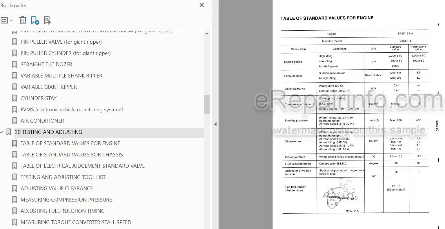
Table Of Standard Values For Engine
Table Of Standard Values For Chassis
Table Of Electrical Judgement Standard Valve
Testing And Adjusting Tool List
Adjusting Value Clearance
Measuring Compression Pressure
Adjusting Fuel Injection Timing
Measuring Torque Converter Stall Speed
Measuring Hydraulic Pressure
Bleeding Air From Hydraulic Cylinder
Adjusting Linkage
Troubleshooting
-TROUBLESHOOTING
Preparation For Troubleshooting
Position Of Connectors
-DISASSEMBLY AND ASSEMBLY
Precautions when carrying out operation
Starter Motor
Fan Belt
Alternator
Engine Oil Cooler
Fuel Injection
Water Pump
Turbo Charger
After Cooler
Nozzle Holder
Cylinder Head
Radiator
Fuel Tank
PTO
Torque Converter Oil Cooler
Engine
Chassis-Related Parts from Engine
Torque Converter
Torque Converter
Torque Converter Relief Valve
Torque Converter Regulator Valve
Torqflow Transmission
Torqflow Transmission
No. 1,3 Carriers and No. 1,2 Sun gears and bearing cage
No. 4 Housing and No. 5,6 Gears and PTO Shaft
Torqflow Transmission
No. 4 Housing and No. 5,6 Gears and PTO Shaft
No. 1,2 Sun Gears and Bearing Cage
Torqflow Transmission Lubrication Valve
Transmission Control Valve
Transmission Control Valve of Steering Clutch
Disassembly / Assembly of Steering Clutch
Bevel Gear Shaft and Bevel Gear
Steering / Brake Interlocking Valve
Steering / Brake Interlocking Valve
Steering Bake Booster
Steering Main Relief Valve
Steering Main Relief Vallve
Brake Assister Cylinder Ass’y
Brake Assister Cylinder Ass’y
Final Drive 1st Pinion
Final Drive
Transmission Pump
Steering Pump
Checking before removal of Track Shoe Assembly
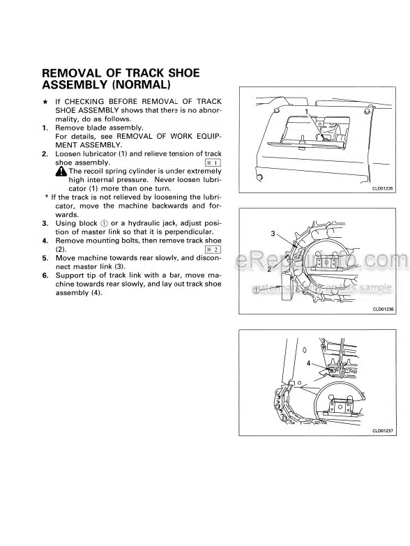
Removal of Track Shoe Assembly (Normal)
Removal of Track Shoe Assembly (When there is abnormality inside track frame)
Installation of Track Shoe Assembly
Truck Line Disassembly and Assembly
Track Shoe
Press-Fitting Jig Dimension Table for Link Press
One link
Master Link
Carrier Roller
Track Roller
Idler
Recoil Spring
Track Frame
Ripper and Blade Control Valve
Blade Tilt Control Valve
Hydraulic Pump
Ripper and Blade Servo Valve
Blade Tilt Servo Valve
Pin Puller Valve
Ripper Selector Control Valve
Ripper Selector Valve
Blade Lift Cylinder
Ripper Lift Cylinder
Ripper Tilt Cylinder
Ripper Cylinder
Pin Puller Cylinder
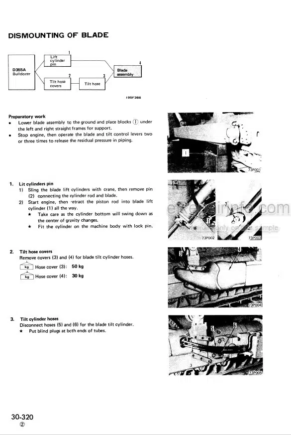
Blade
Variable Giant Ripper
Floor Frame
ROPS Cab
-MAINTENANCE STANDARD
Transmission Pump
Steering Pump
Torque Converter
Transmission Lubrication Relief Valve
Torqflow Transmission
Transmission Control Valve
Bevel Gear Shaft
Steering Clutch
Steering Control Valve
Steering Main Relief Valve
Brake Assister Turomatic Drain Valve
Brake Assister Check Valve
Spring Assist Brake Cylinder
Spring Assist Brake Auto Drain Valve
Steering Brake and Booster
Final Drive
Track Frame
Recoil Spring
Idler
Track Roller
Carrier Roller
Track Shoe (Lubricated track link)
Track (Dry type track link)
Hydraulic Pump
Hydraulic Control Valve
Quike Drop Valve
Ripper Selector Valve and Pilot check Valve
Ripper Pilot Valve
Ripper Pin Puller Valve (for Giant Ripper)
Hydraulic Cylinder
Pin Puller Cylinder (for Giant Ripper)
Servo Valve
Straight Tilt Dozer
Cylinder Stay
Variable Multiple Shank Ripper
Variable Giant Ripper
-DRAWINGS
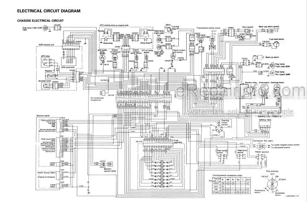
Electrical Circuit Diagram
Location Of Connectors
What you get
You will receive PDF file with high-quality manual on your email immediately after the payment.
Reviews
There are no reviews yet