Factory Shop Manual For Komatsu Bulldozer Hydraulic System. Manual Contains Illustrations, Instructions, Diagrams For Step By Step Remove And Install, Assembly And Disassembly, Service, Inspection, Repair, Troubleshooting, Tune-Ups.
Format: PDF
Language: English
Pages: 114
Number: 3072519M2
Hydraulic Diagrams: Yes
Model
Komatsu Bulldozer Hydraulic System
D600C
D600D
600C
L600D
Contents
-DESCRIPTIONS, FAULT DIAGNOSIS, TESTS AND ADJUSTMENTS
Description
Oil Tank With 3-Spool Control Valve (L600D)
Mounting Plate With 3-Spool Control Valve (L600D)
Oil Tank With 3-Spool Control Valve (L600D From Serial No. 3317 20 114)
Mounting Plate With 3-Spool Control Valve (L600D From Serial No. 3317 20 114)
Hydraulic Circuit Diagram (600C)
Hydraulic Circuit Diagram (D600C)
Hydraulic Circuit Diagram (D600D)
Hydraulic Circuit Diagram (L600D)
Dual-Pressure Hydraulic Circuit Diagram (L600D From Serial No. 3317 20 114)
Electrical Circuit Diagram – Automatic Return To Dig And Boom Kickout Systems (L600D)
Automatic Return To Dig System – Operation And Adjusting (L600D)
Hydraulic Pump (L600D/ D600D)
3-Spool Control Valve (D600D With Blade Tilt System)
3-Spool Control Valve – Components And Operation (L600D)
Pilot Operated Pressure Relief Valve – Components (All Models)
Dual-Pressure Relief Valve – Components (L600D From Serial No. 3317 20 114)
Shock Valve – Components (All Models)
Oil Cooler By-Pass Valve – Components (All Models)
Shift Control Linkage (All Models)
Fault Diagnosis Table (600C / L600D)
Fault Diagnosis Table (D600C/ D600D)
Fault Diagnosis Table — Hydraulic Pump And Pressure Relief Valve (All Models)
Pressure Test Manifold (L600D / D600D)
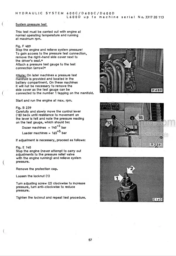
System Pressure Test (All Models Except L600D From Serial No. 3317 20 114)
System Pressure Test (L600D From Serial No. 3317 20 114)
Testing The Check Valves (All Models)
-INSTRUCTIONS FOR REMOVING, DISASSEMBLING, RE-ASSEMBLING AND REPLACING COMPONENTS
Removing And Replacing The Hydraulic Pump (All Models)
Removing And Replacing The Pressure Relief Valve (All Models)
Disassembling And Re-Assembling The Pressure Relief Valve (All Models Except L 600 From Serial No. 3317 20 114)
Removing And Replacing The Control Valve (All Models)
Disassembling And Re-Assembling The Shift Control Linkage (All Models)
Removing And Replacing A Lift Cylinder (D600C/ D600D)
Disassembling And Re-Assembling A Lift Cylinder (All Models)
Removing And Replacing A Lift Cylinder Pivot Yoke Assembly (D600C / D600D)
Disassembling And Re-Assembling A Pivot Yoke Assembly (D600C / D600D)
Removing And Replacing A Bucket Cylinder (600C / L600D)
Disassembling And Re-Assembling A Bucket Cylinder (600C / L600D)
Lift And Bucket Cylinders – Components (600 C Up To Serial No. 310 06 098)
Lift Cylinder – Components (L600D)
Lift Cylinder – Components (D600D From Serial No. 309 07 073)
Bucket Cylinder – Components (L600D)
What you get
You will receive PDF file with high-quality manual on your email immediately after the payment.


Reviews
There are no reviews yet