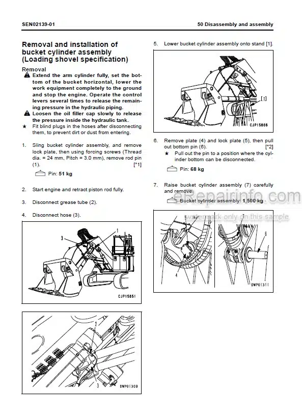
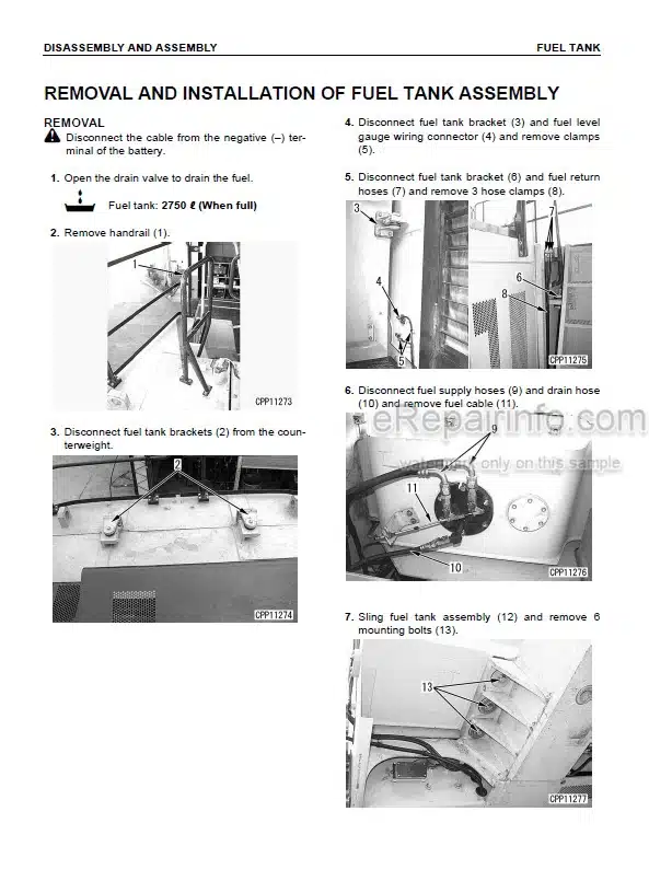
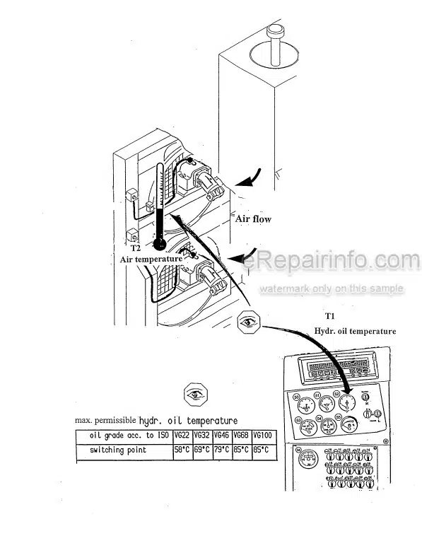
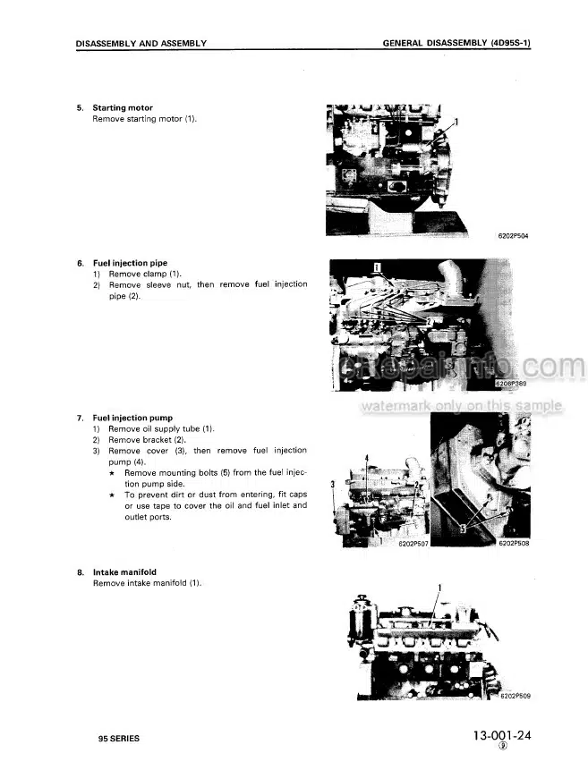
Factory Shop Manual For Komatsu Hydraulic Excavator. Manual Contains Illustrations, Instructions, Diagrams For Step By Step Remove And Install, Assembly And Disassembly, Service, Inspection, Repair, Troubleshooting, Tune-Ups.
Format: PDF
Language: English
Pages: 1519
Number: SEN01607-19 (may 2010)
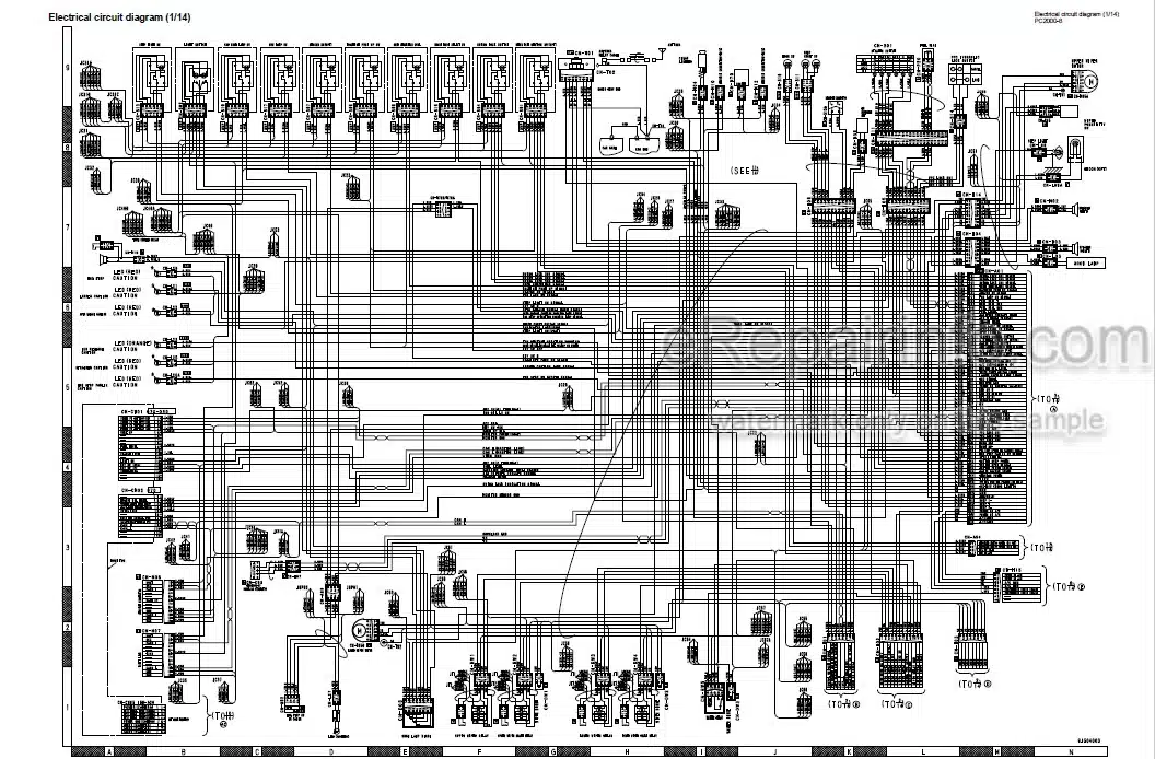
Wiring Diagrams: Yes
Hydraulic Diagrams: Yes
Model
Komatsu Hydraulic Excavator
PC2000-8
SN 20001 And Up
Contents
-INDEX AND FOREWORD
Index
Foreword And General Information
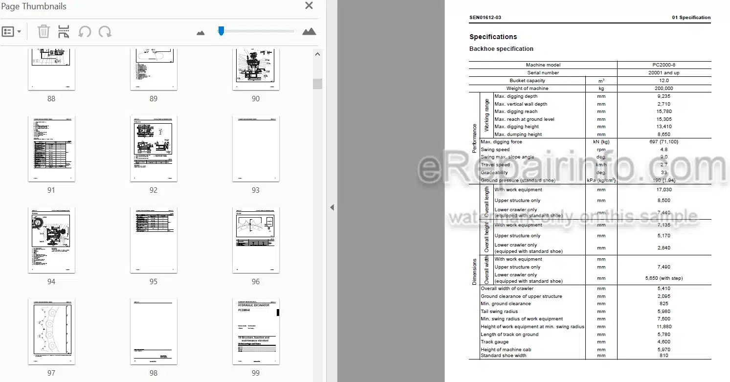
-SPECIFICATION
Specification And Technical Data
-STRUCTURE, FUNCTION AND MAINTENANCE STANDARD
Engine And Cooling System
Power Train
Undercarriage And Frame
Hydraulic System
Work Equipment
Cab And Its Attachments
Electrical System
-STANDARD VALUE TABLE
Standard Service Value Table
-TESTING AND ADJUSTING
Tools For Testing, Adjusting, And Troubleshooting
Measuring Engine Speed
Testing Air Boost Pressure
Testing Exhaust Temperature
Testing Exhaust Color
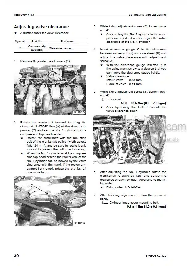
Adjusting Valve Clearance
Testing Compression Pressure
Testing Blow-By Pressure
Testing Engine Oil Pressure
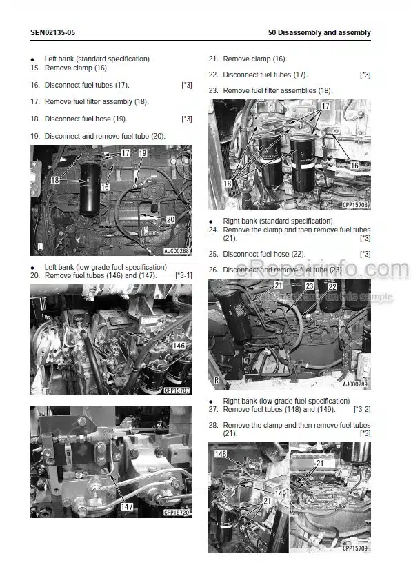
Handling Fuel System Parts
Releasing Residual Pressure In Fuel System
Testing Fuel Pressure
Reduced Cylinder Mode Operation
No-Injection Cranking
Testing Leakage From Pressure Limiter And Return Rate From Injector
Bleeding Air From Fuel Circuit
Bleeding Air From Fuel Circuit (Low-Grade Fuel Specification)
Testing Fuel System For Leakage
Testing And Adjusting Alternator Belt Tension
Testing And Adjusting Air Conditioner Compressor Belt Tension, Handling Controller High-Voltage Circuit
Testing Swing Circle Bearing Clearance
Remaining Pressure Relief From HIC Circuit
Gas Filling In HIC Circuit Accumulator
Bleeding Air From HIC Circuit And Supplying Oil To It
Testing And Adjusting Track Shoe Tension
Testing And Adjusting Work Equipment, Swing And Travel Circuit Oil Pressures
Testing And Adjusting Control Circuit Oil Pressure (Output Pressure Of Self Pressure Reducing Valve)
Testing And Adjusting Main Pump Control Signal
Measuring Fan Speed
Measuring Fan Pump EPC Solenoid Current
Measuring Fan Pump EPC Solenoid Valve Output Pressure
Oil Pressure Measuring Points For Pump Discharge Pressure Or Jet Sensor Differential Pressure
Measuring PPC Valve Output Pressure
Measuring Solenoid Valve Outlet Pressure
Adjusting Work Equipment And Swing PPC Valve
Testing And Adjusting Travel Deviation
Testing Work Equipment Hydraulic Drift Cause Portion
Testing Oil Leakage
Remaining Pressure Relief From Hydraulic Circuit
Air Bleeding From Each Component
Testing And Adjusting Auto Grease System
Adjusting Mirrors
Testing And Adjusting Clearance Of Hydraulic Ladder Proximity Switch
Testing And Adjusting Position Of Hydraulic Ladder Position Sensor Plate
Testing And Adjusting Clearance To Service Arm Proximity Switch
Special Functions Of Machine Monitor
Handling Controller Voltage Circuit
VHMS Controller Initial Setting Procedure
Precautions For Replacing VHMS Controller
Preparation Work For Troubleshooting Of Electrical System
PM-Clinic Service
Measurement Procedure
-TROUBLESHOOTING
Failure Code Table And Fuse Locations
General Information On Troubleshooting
Troubleshooting Of Electrical System (E-Mode)
Troubleshooting Of Hydraulic And Mechanical System (H-Mode)
Troubleshooting Of Mechanical System (S-Mode)
-DISASSEMBLY AND ASSEMBLY
General Information On Disassembly And Assembly
Engine And Cooling System
Engine
Power Train
Undercarriage And Frame
Hydraulic System
Work Equipment
Cab And Its Attachments
Electrical System
-DIAGRAMS AND DRAWINGS
Hydraulic Diagrams And Drawings
Electrical Diagrams And Drawings
What you get
You will receive PDF file with high-quality manual on your email immediately after the payment.
Reviews
There are no reviews yet