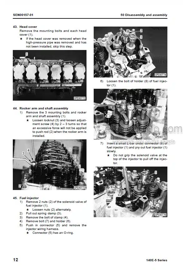
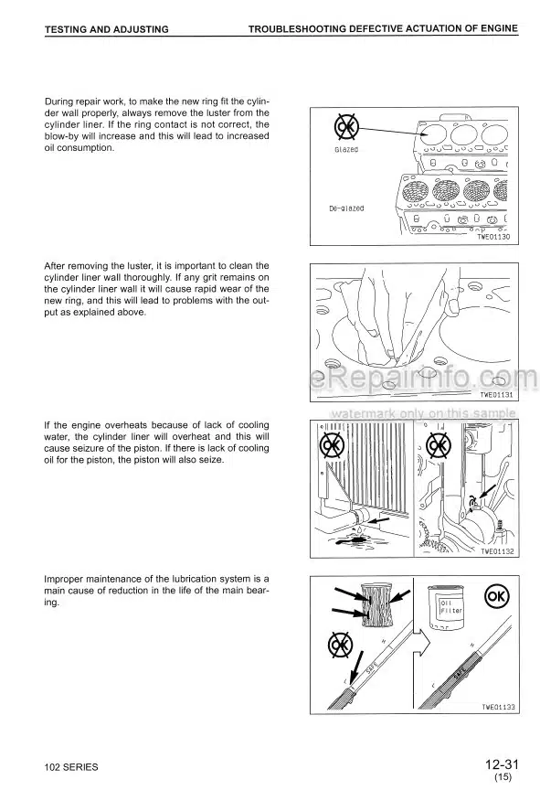
Factory Shop Manual For Komatsu Crane. Manual Contains Illustrations, Instructions, Diagrams For Step By Step Remove And Install, Assembly And Disassembly, Service, Inspection, Repair, Troubleshooting, Tune-Ups.
Format: PDF
Language: English
Pages: 1910
Number: SEBM008905 (november 1997)
Bookmarks: Yes
Wiring Diagrams: Yes
Hydraulic Diagrams: Yes
Model
Komatsu Crane
LW250-5
X-Shaped Outrigger Specification
SN 50001 And Up
H-Shaped Outrigger Specification
Contents
-GENERAL
Specification Drawing
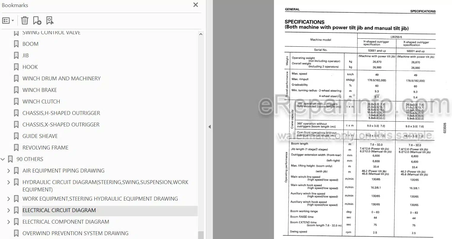
Specifications
Working Radius-Lifting Height Chart
Rated Overall Load Table
Minimum Intersecting Aisle Width
Weight Table
List Of Lubricants And Water
-STRUCTURE AND FUNCTION
Powertrain
Engine Speed Set Cylinder
Damper
Transmission Hydraulic Piping Diagram
Torque Converter, Transmission Hydraulic Circuit Diagram
Torque Converter, Transmission Hydraulic System Schematics
Torque Converter
PTO Clutch
Transmission
Transmission Control Valve
Proportional Solenoid Valve
Axle
Brake
Parking Brake
Tires
Swing Circle
Steering Wheel
Rear Steering Lock System
Suspension System
Air Circuit Diagram
Air Equipment Piping Drawing
Air Governor
Accelerator Control Valve
Accelerator Control Cylinder
Exhaust Brake Selector Valve
Exhaust Brake Butterfly Valve
Brake Air System
Brake Control Valve
Brake Booster
Brake Shuttle Valve
Auxiliary Brake Valve
Parking Brake Valve
Parking Brake Chamber
Rear Steering Lock Air System
Rear Steering Lock Valve
Rear Steering Lock Cylinder
Centralized Greasing Pump
Hydraulic, Hot Water, Air Center Swivel Joint
Hydraulic Circuit Diagram
Work Equipment, Steering Hydraulic Equipment Drawing
Main Control Valve
Swing Hydraulic System
Swing Valve
Swing Motor, Machinery
Swing Holding Brake And Brake Solenoid Valve
Swing Brake Valve
Swing Free/Lock Selector Valve
Steering Hydraulic System
Steering Unit
Priority Valve
Steering Mode Selector Valve
Rear Wheel Steering Selector Valve
Reverse Steering Compensation Valve
Suspension Hydraulic System
Suspension Selector Valve
Suspension Lock Valve
Suspension Pilot Check Valve
Outrigger Hydraulic System
Outrigger Selector Valve
Collection Check Valve
Outrigger Individual Valve
Outrigger Merge Selector Valve
Outrigger Jack Pilot Check Valve
Pedal PPC Valve
Lever PPC Valve
Relief Valve
Boom Hydraulic System
Unload Pilot Valve
Boom Telescope Selector Valve
Boom Cylinder
Winch Hydraulic System
Winch Motor
Winch Clutch Valve
Winch Brake Master Cylinder
Overrun Prevention Valve
Flow Priority Valve
Charge Valve
Air Conditioner
Boom
Jib
Main Hook
Auxiliary Hook
Winch
Winch Drum
Winch Clutch
Winch Brake
Chassis, X-Shaped Outrigger
Revolving Frame, Guide Sheave
Electric Circuit Diagram
Electrical Component Diagram
Overwind Prevention System Drawing
Overload Safety System Drawing
Electric Swivel Joint{Slip Ring)
Multiple Data Transfer (MDT) System
Automatic Gear Shift System (AESC)
Gear Shift Lever(Trim Switch)
Moment Limiter(Overload Prevention System)
Outline, Operation Of Electric Circuits
-TESTING AND ADJUSTING
Standard Value Table For Engine
Standard Value Table For Chassis
Standard Value Table For Electrical Related Parts
Tools For Testing, Adjusting And Troubleshooting For Engine
Adjusting Valve Clearance
Measuring Compression Pressure
Testing And Adjusting Fuel Injection Timing
Measuring Engine Oil Pressure
Testing And Adjusting Fan Belt Tension
Testing And Adjusting Air Conditioner Compressor Belt Tension
Measuring Engine Speed
Measuring Blow-By Pressure
Measuring Exhaust Temperature
Measuring Exhaust Color
Measuring Oil Pressure
Measuring Leakage Of Oil
Procedure For Flushing Hydraulic Oil
Measuring And Adjusting Air Pressure
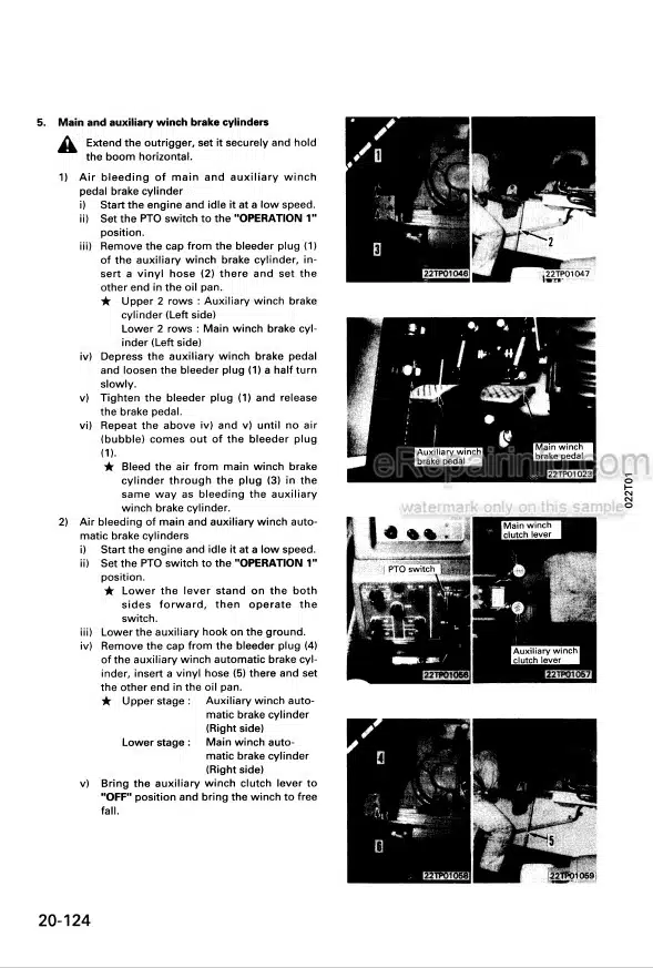
Bleeding Air
Measuring Steering Wheel Play
Adjusting Minimum Turning Radius Of Steering
Testing And Adjusting Toe-In
Testing And Adjusting Parking Brake Effect
Adjusting Engine Control
Method For Adjusting Engine Stop Motor Cable
Adjusting Brake Pedal
Adjusting Winch Brake
Adjusting Winch Drum Lock
Adjusting Main, Auxiliary Winch Clutch
Adjusting Telescope/Auxiliary Winch Pedal
Adjusting Lever Stand, Lock Lever
Adjusting Telescope Wire Rope
Adjusting Limit Switch
Testing And Adjusting Proximity Switch
Checks Before Starting For Overload Prevention System
Setting Model Selector Switch For Overload Safety System
Method Of Displaying Service Mode For Overload Prevention System
Troubleshooting
-DISASSEMBLY AND ASSEMBLY
Precautions When Carrying Out Operation
Special Tool List
Sketches Of Special Tools
Alternator
Engine Oil Cooler
Fuel Injection Pump
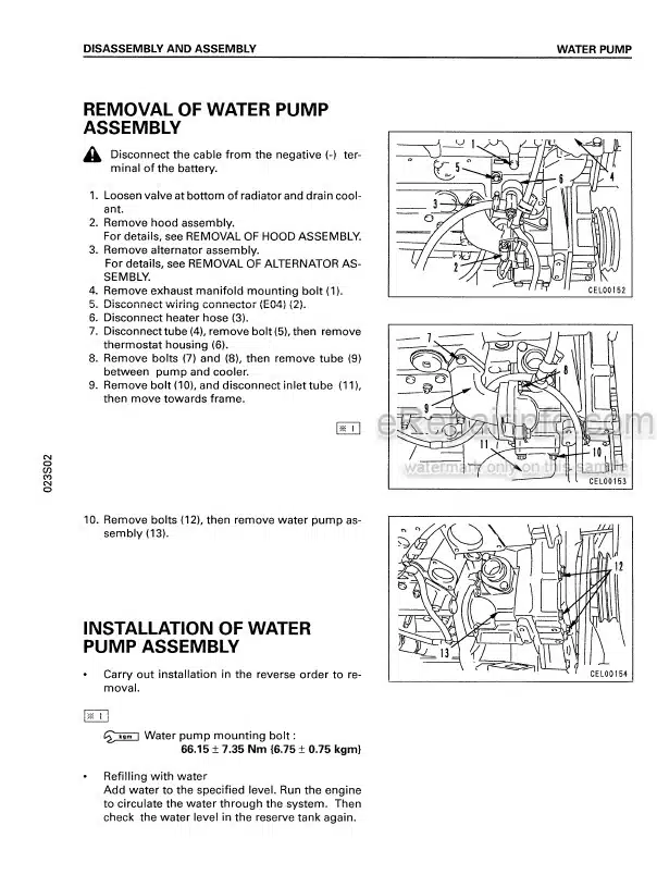
Water Pump
Thermostat
Muffler
Exhaust Brake
Turbocharger
Nozzle Holder
Engine Front Seal
Engine Rear Seal
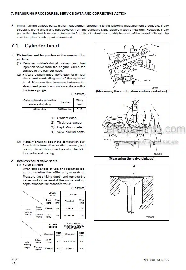
Cylinder Head
Air Compressor
Engine
Radiator, Power Train Oil Cooler, Hydraulic Cooler
PTO Set Cylinder
Accelerator Control Cylinder
Fuel Tank
Damper
Damper Cover
Transmission
Transmission
Torque Converter
Transmission Control Valve
Hi/Lo, 2WD/4WD Selector Solenoid Valve
Front Axle
Rear Axle
Axle
Differential
Parking Brake Shoe
Wheel Assembly
Wheel Brake Disc Plate
Rear Steering Lock Cylinder
Suspension Lock Cylinder
Suspension Lift Valve
Swing Circle
Air Governor
Air Regulator Valve
Wheel Brake Valve
Wheel Brake Air Master
Parking Brake Solenoid Valve
Auxiliary Brake Solenoid Valve
Exhaust Brake Solenoid Valve
Wheel Brake Caliper
Parking Brake Chamber
Hydraulic Tank Assembly
Winch, Boom, PPC Pump
Transmission, Steering(Outrigger),Swing Pump
Maximum Flow Control Valve
Center Swivel Joint
Steering Priority Valve
Steering Valve
Emergency Steering Pump
Emergency Steering Pump, Motor
Steering Mode Solenoid Valve
Steering Cylinder
Outrigger Control Valve
Outrigger Jack Cylinder Check Valve
Outrigger Individual Solenoid Valve
Outrigger Slide Cylinder(X-Shaped)
Outrigger Jack Cylinder(X-Shaped)
Outrigger Slide Pilot Check Valve
Outrigger Slide Pilot Check Valve
PPC Relief Valve
Boom Hoist, Main Winch, Auxiliary Winch PPC Valve
Jib Power Tilt, Swing PPC Valve
Boom Telescope PPC Valve
Lever Control PPC Valve
Pedal Control PPC Valve
Winch Brake Master Cylinder
Winch Brake Master Cylinder
Boom, Winch Control Valve
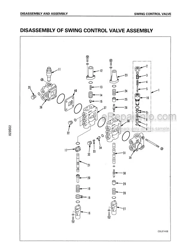
Swing Control Valve
Swing Control Valve
Swing PPC Shuttle Valve
Swing Brake Solenoid Valve
Swing Motor, Swing Machinery
Swing Free Solenoid Valve
Swing, Outrigger Merge Valve
Swing, Outrigger Merge Selector Solenoid Valve
Accumulator
Accumulator
Accumulator Charge Valve
Winch Clutch Valve
Main Auxiliary Winch Motor
Boom Hoist Cylinder
Boom Telescope Order Selector Solenoid Valve
Pedal Control Selector Valve
Winch Brake Caliper
PPC Unload Solenoid Valve
Main Unload Solenoid Valve
Jib Rotation Cylinder
Jib Power Tilt Cylinder
Jib Lock Cylinder
Hydraulic Cylinder
Jib Extend/Stow Solenoid Valve
PTO Clutch, Suspension Lock Pilot Selector Valve
Air Conditioner Compressor Motor
Air Conditioner Compressor Motor Check Valve
Air Conditioner Motor Check Valve
Accelerator Control Valve
Main Winch, Auxiliary Winch
Boom
Boom Telescope Cylinder
Jib
Outrigger(X-Shaped)
Operator’s Cab
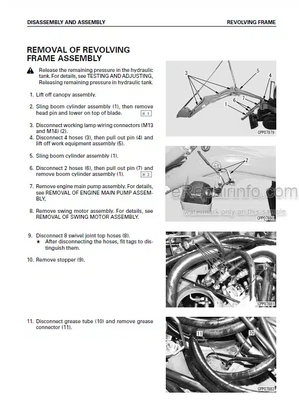
Revolving Frame
Hood
Air Conditioner Compressor
Air Conditioner Condenser
Upper MDT Controller
Moment Limiter Controller
Lower MDT Controller
Transmission Controller
Jib Transmission Module
Slip Ring
Jib Tilt Cord Reel
Jib Extend Cord Reel
Outrigger Length Sensor
Boom Length Sensor
Front Hose Reel
Rear Hose Reel
-MAINTENANCE STANDARD
Torque Converter
PTO Clutch
Transmission
Transmission Control Valve
Axle
Check Valve
Suspension System
Brakes
Parking Brake
Boom Cylinder
Power Tilt Cylinder
Lever PPC Valve
Pedal PPC Valve
Relief Valve
Swing Control Valve
Boom
Jib
Hook
Winch Drum And Machinery
Winch Brake
Winch Clutch
Chassis, H-Shaped Outrigger
Chassis, X-Shaped Outrigger
Guide Sheave
Revolving Frame
-OTHERS
Air Equipment Piping Drawing
Hydraulic Circuit Diagram{Steering, Swing, Suspension, Work Equipment)
Work Equipment, Steering Hydraulic Equipment Drawing
Electrical Circuit Diagram
Electrical Component Diagram
Overwind Prevention System Drawing
Overload Safety System Drawing
System Construction Chart
Connector Allocation Diagram
Moment Limiter System Electrical Circuit Diagram
Boom
Chassis, H-Shaped Outrigger
Chassis, X-Shaped Outrigger
What you get
You will receive PDF file with high-quality manual on your email immediately after the payment.

Reviews
There are no reviews yet