Factory Instruction For Repair For Bomag Tandem Vibratory Roller. Manual Contains Illustrations, Instructions, Diagrams For Step By Step Remove And Install, Assembly And Disassembly, Service, Inspection, Repair, Troubleshooting, Tune-Ups.
Format: PDF
Language: English
Pages: 318
Number: 00819132 (september 1991)
Wiring Diagrams: Yes
Hydraulic Diagrams: Yes
Model
Bomag Tandem Vibratory Roller
BW161AD
BW202AD
Contents
-GENERAL INFORMATION
Safety Regulations
General Repair Instructions
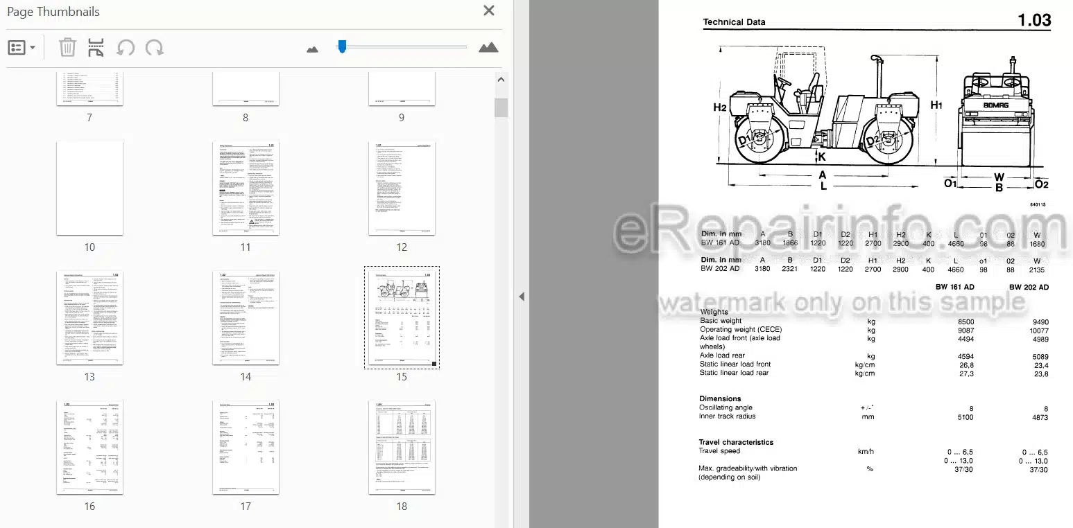
Technical Data
Torques
Connecting Points
Special Tools
-ENGINE
Checking The Diesel Engine Speed
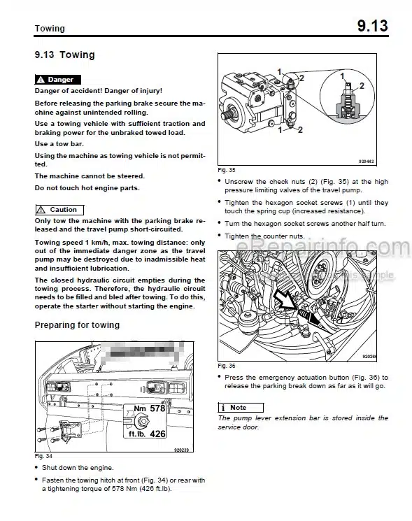
Dismounting And Installing The Engine
Preparing The Engine For Operation
-TRAVEL SYSTEM
Pressure Tests In The Travel System
Travel Pump High Pressure Test
Trouble Shooting Chart
Dismounting And Installing The Travel Motor
Repair Survey
General Notes For Repair
Repairing The Travel Motor
Repairing The Brake
Dismounting And Installing The Travel Pump
Exchanging The Coupling For The Travel Pump
Survey Of Procedures For Sealing And Changing The Travel/Vibration Pump
General Notes On Repairs Travel Vibration Pump
Replacing The Seallock Nut 1
Sealing The Drive Shaft Of The Travel/Vibration Pump
Sealing Replacing The Control Valve And The Pressure Cut-Off Valve
Sealing The Hydraulic Control 4 On The Travel/Vibration Pump
Sealing/Replacing The Pressure Relief Valve 5 In The Travel System
Sealing/Replacing The Pressure Relief Valve In The Vibration System
Sealing/Cleaning The Charge Pressure Relief Valve 7
Sealing The Housing Cover 8
Sealing/Replacing The Way Valve
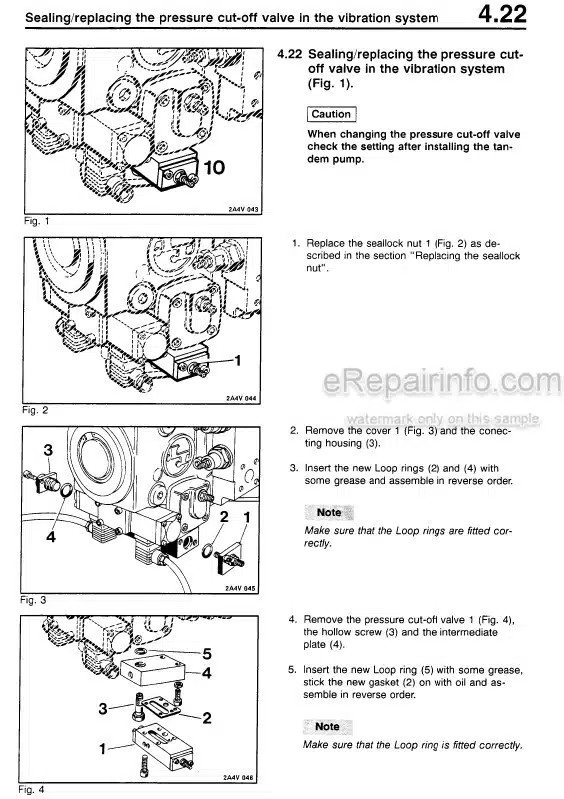
Sealing/Replacing The Pressure Cut-Off Valve In The Vibration System
Sealing The Timing Screw 11
Sealing/Replacing The Flushing Valve
Sealing The Bearing Cage Guide 13
Cleaning The Nozzles 14
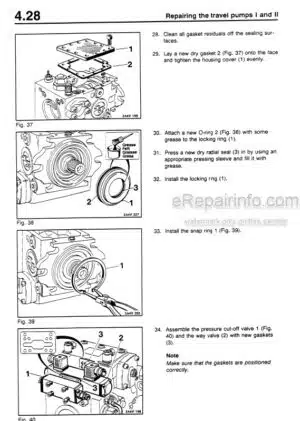
Repairing The Travel Vibration Pump
General Notes On Repairs Travel Vibration Pump
Repairing The Vibration Pump
Repairing The Travel Pump
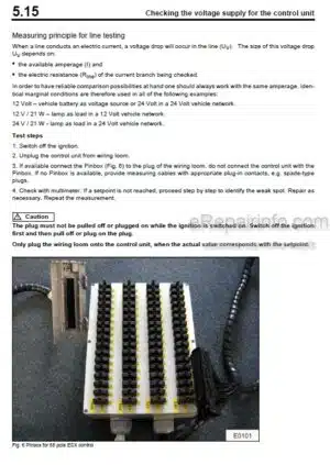
Repairing The Control Unit
Flushing Schematic Travel System
Flushing The Travel Circuit
Filling The Hydraulic System
-VIBRATION
Checking The Speed Of The Exciter Shaft
Trouble Shooting Chart
Dismounting And Installing The Vibration Pump For The Front Drum
Exchanging The Coupling For The Vibration Pump
Dismounting And Installing The Drum
Exchanging The Rubber Buffers
General Survey For Sealing And Exchange Procedures For The Vibration Pump
General Notes For Repairs
Changing The Seallock Collar Nut 1
Sealing The Drive Shaft 2
Sealing The Hydraulic Control Unit 3
Sealing Changing The High Pressure Relief Valves 4
Sealing Cleaning The Charge Pressure Relief Valve 5
Sealing The Housing Cover 6
Sealing/Changing The Way Valve 7
Sealing/Changing The Pressure Cut-Off Valve 8
Sealing/Changing The Flushing Valve 9
Sealing The Bearing Cage Guides 10
Cleaning The Nozzles 11
Sealing The Timing Screw 12
Sealing The Cover 13
Repairing The Vibration Pump
Repair Survey Vibration Pump
General Notes For Repairs
Repairing The Vibration Pump
Repair Survey Of The Drum
Disassembling And Assembling The Drum
Disassembling And Assembling The Change Over Weight
Dismounting And Installing The Vibration Motor
Exchanging The Coupling Sleeve
Repair Survey Vibration Motor
General Notes For Repair
Sealing The Vibration Motor
Repairing The Vibration Motor Drive
Flushing Schematic For The Rear Vibration Circuit
Flushing The Rear Vibration Circuit
Flushing Schematic For The Front Vibration Circuit
Flushing The Front Vibration Circuit
-STEERING
Checking, Adjusting The Steering Pressure
Trouble Shooting Chart
Dismounting And Installing The Steering Cylinders
Repairing The Steering Cylinder
Dismounting And Installing The Steering/Charge Pump
Repairing The Steering Charge Pump
Dismounting And Installing The Steering Unit
Repairing The Steering Unit
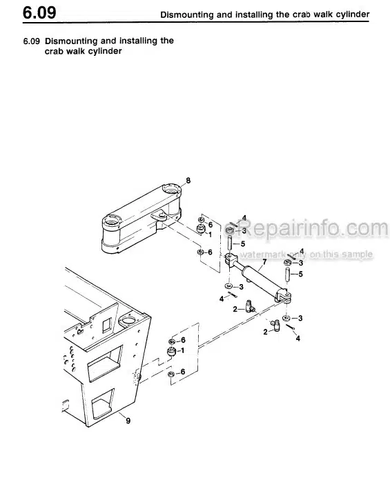
Dismounting And Installing The Crab Walk Cylinder
Dismounting And Installing The Oscillating Articulated Center Joint
Repairing The Oscillating Articulated Center Joint
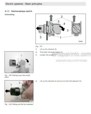
-ELECTRIC SYSTEM
General Notes For Trouble Shooting
Important Electric Symbols And Designations
Overall View Of Instrument Panel
Description Of Current Supply
Description Of Fuses
Description Of Starting
Description Of Charge And Start Control
Description Of Brake
Description Of Brake Control
Description Of Vibration System
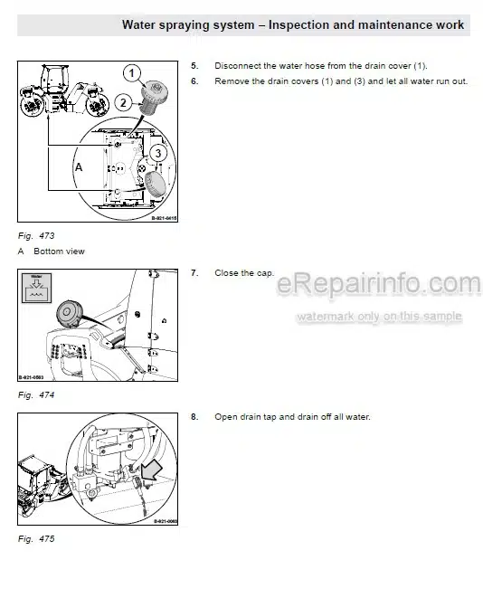
Description Of Water Sprinkler System
Description Of Relay Board
Description Of Monitoring Module
Description Of Engine Oil Control
Testing The Monitoring Module
Testing The Relay Board
Testing The Relay Board For The Hydraulic Oil Filters
Testing The Relay Board For The Water Sprinkler System
-CIRCUIT DIAGRAMS
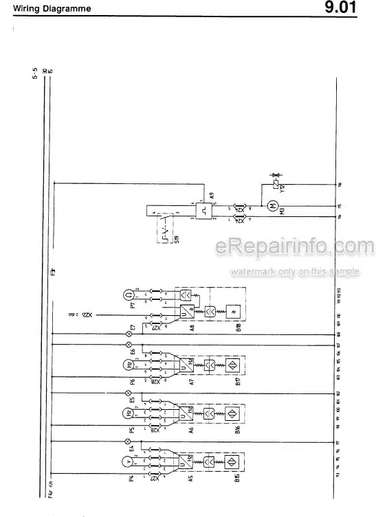
Wiring Diagramme
Hydraulic Schematic
What you get
You will receive PDF file with high-quality manual on your email immediately after the payment.
Reviews
There are no reviews yet