Factory Service Manual For Bomag Single Drum Roller. Manual Contains Illustrations, Instructions, Diagrams For Step By Step Remove And Install, Assembly And Disassembly, Service, Inspection, Repair, Troubleshooting, Tune-Ups.
Format: PDF
Language: ENG
Pages: 1392
Number: 00840190 (december 2016)
Bookmarks: Yes
Searchable: Yes
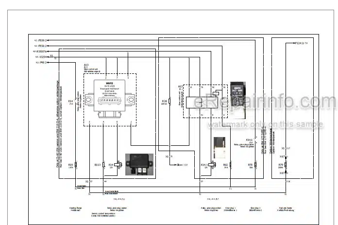
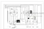
Wiring Diagrams: Yes
Hydraulic Diagrams: Yes
Model
Bomag Single Drum Roller
BW211D-40
BW211PD-40
BW212D-40
BW212PD-40
BW213D-40
BW213PD-40
S/N 101 583 48 1095>
S/N 861 583 55 1001>
S/N 861 583 56 1001>
S/N 101 582 42 1940>
S/N 101 582 43 2399>
S/N 101 582 44 1209>
S/N 101 582 47 1053>
S/N 101 582 48 1239>
S/N 101 582 49 1019>
Contents
-GENERAL
Introduction
Concerning Your Safety
Notes On Repair
Fuels And Lubricants
List Of Fuels And Lubricants
-OVERVIEW OF MACHINE
Diesel Engine
Travel / Vibration Pump
Drum
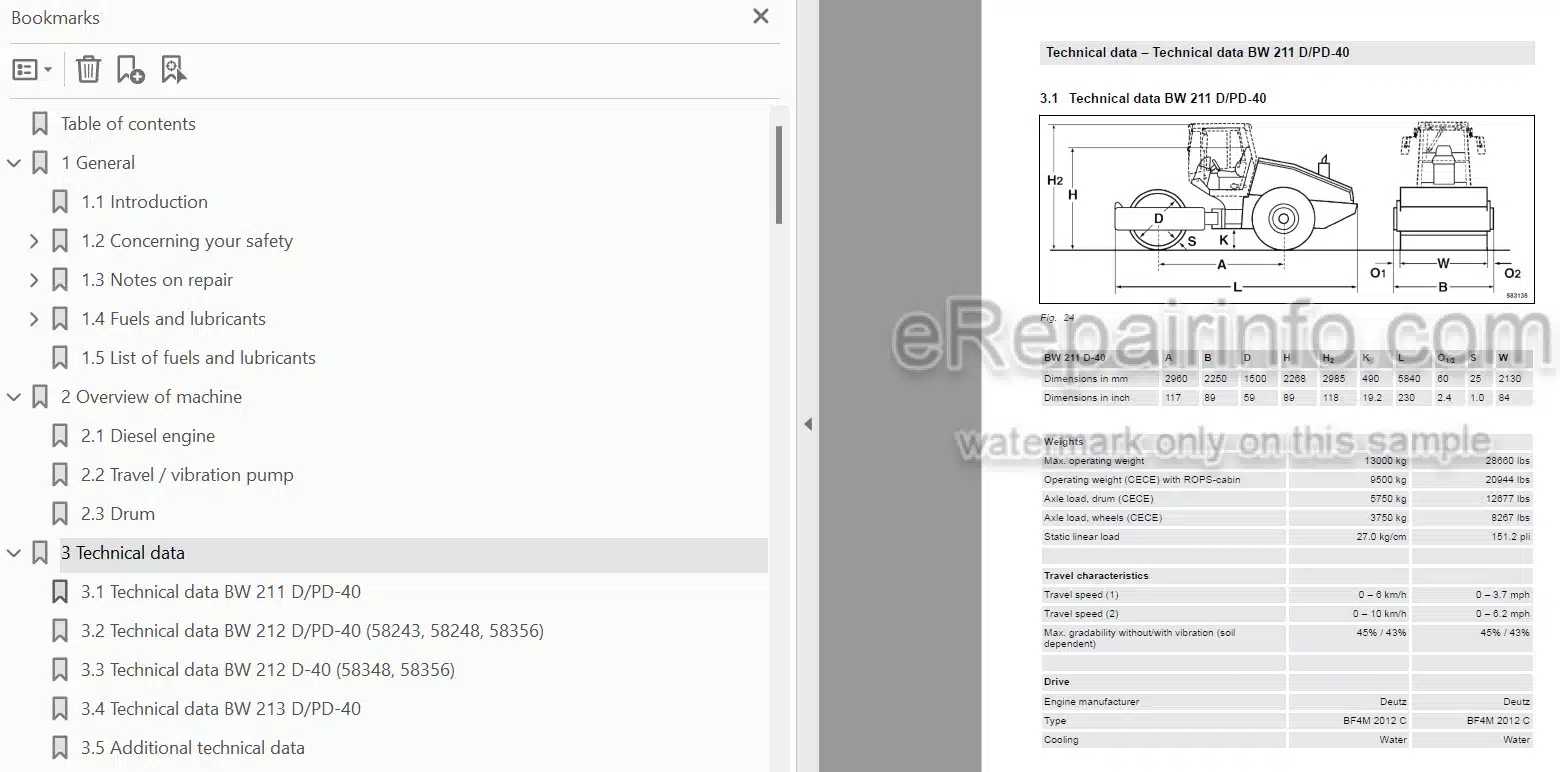
-TECHNICAL DATA
Technical Data BW 211 D/PD-40
Technical Data BW 212 D/PD-40 (58243, 58248, 58356)
Technical Data BW 212 D-40 (58348, 58356)
Technical Data BW 213 D/PD-40
Additional Technical Data
-ELECTRIC SYSTEMS
Table Of Fuels And Lubricants
Central Electrics
Fuse Assignment
Operator’s Stand
Wiring
Starting The Engine With Jump Leads
Proximity Switches On Travel Lever, B13 And B14
Differential Pressure Switch For Hydraulic Oil Filter, B21
Level Sensor In Diesel Tank, R03
Float Switch, Coolant Tank, B55
Air Filter Vacuum Switch, B03
Sensor For Water In Fuel, B124
Fuel Pre-Heating, R79
Oil Pressure Switch, B06
Coolant Temperature Switch, B30
Boost Fuel Solenoid Valve, Y01
Solenoid Actuator To Shut Down The Engine, Y13
Engine Solenoid Actuator, Y120
Charge Control Light, Engine Tachometer
Heating Flange On Engine, R19
Messx, A83
Acceleration Transducer, B62
Control Unit For Air Conditioning, A108
Module For Seat Contact Monitoring, A68
Vibration Module, K04
Speedometer Module, A05
Telemecanique Switch
Deutsch Plug, Series DT And DTM
Magnetic Coil Plug
Inspection And Maintenance Work
-DIESEL ENGINE
Diesel Engine, General
Service Side
Starter Side
Lubrication Oil Circuit
Coolant Circuit
Replacing The Thermostat
Fuel Supply
Injection System
Injection Pump Replacement During Service
Injection Valve Replacement During Service
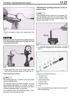
Checking / Repairing Injection Valves
Checking The Compression
Inspection And Maintenance Work
-HYDRAULIC SYSTEM
Overview Of Travel/Vibration Pump Connections
Open And Closed Hydraulic Circuit
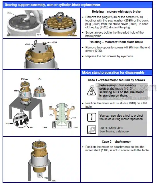
Hydraulic Units
Charge Circuit
Travel Circuit
Vibration Circuit
Steering Circuit
Tests And Adjustments
Flushing And Bleeding
Inspection And Maintenance Work
-AIR CONDITIONING
Overview
Physical Principles
Refrigerant R134A
Compressor Oil / Refrigeration Oil
Working Principle Of The Air Conditioning System
Monitoring Devices
Description Of Components
Compressor
Emptying In Case Of Repair
Drying And Evacuation
Filling Instructions
Steam Table For R134A
Inspection And Maintenance Work
-CABIN ASSEMBLY BEFORE INITIAL COMMISSIONING
Preparations
Cabin Assembly
Final Function Tests And Checks
-REPLACING THE CAB WINDOW PANES
Assembly Of Window Panes
Auxiliary Materials
Removing And Installing The Window Pane
-OSCILLATING ARTICULATED JOINT
Overview Oscillating Articulated Joint
Removing And Installing The Oscillating Articulated Joint
Dismantling The Oscillating Articulated Joint
Assembling The Oscillating Articulated Joint
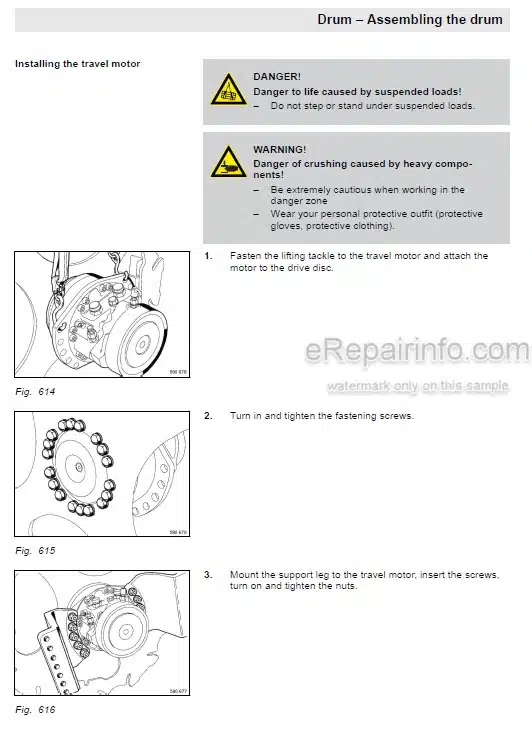
-DRUM
Assembly Of Padfoot Shell
Overview Drum
Removing And Installing The Drum
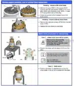
Dismantling The Drum
Dismantling And Assembling The Change-Over Weight
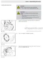
Assembling The Drum
Changing The Rubber Buffers, Adjusting The Pretension
Inspection And Maintenance Work
-DRIVE AXLE
Drive Axle
Checks Prior To Start Up
Every 250 Operating Hours
Every 1000 Operating Hours
As Required
-TROUBLESHOOTING
Preliminary Remarks
Emergency Procedures
Troubleshooting, Electrical Systems
Troubleshooting, Diesel Engine
Trouble Shooting, Hydraulics
Trouble Shooting, Air Conditioning System
-DISPOSAL
Final Shut-Down Of Machine
-SPECIAL TOOLS
Special Tools, Electrics
Special Tools, Hydraulic System
Special Tools For Oscillating Articulated Joint
Special Tools, Drum
INDEX
-APPENDIX
Supplier Documentation
Circuit Diagrams
What you get
You will receive PDF file with high-quality manual on your email immediately after the payment.

Reviews
There are no reviews yet