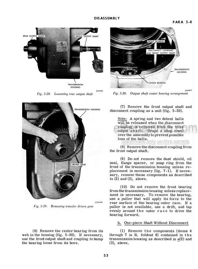
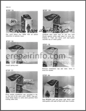
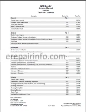
Factory Service Manual For Case Loader. Manual Contains Illustrations, Instructions, Diagrams For Step By Step Remove And Install, Assembly And Disassembly, Service, Inspection, Repair, Troubleshooting, Tune-Ups.
Format: PDF
Language: English
Pages: 415
Number: 9-78236
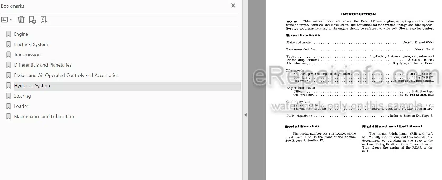
Bookmarks: Yes
Wiring Diagrams: Yes
Hydraulic Diagrams: Yes
Model
Case Loader
W26
Contents
-ENGINE
Introduction
Stall Checks
Removing The Engine
Installing The Engine
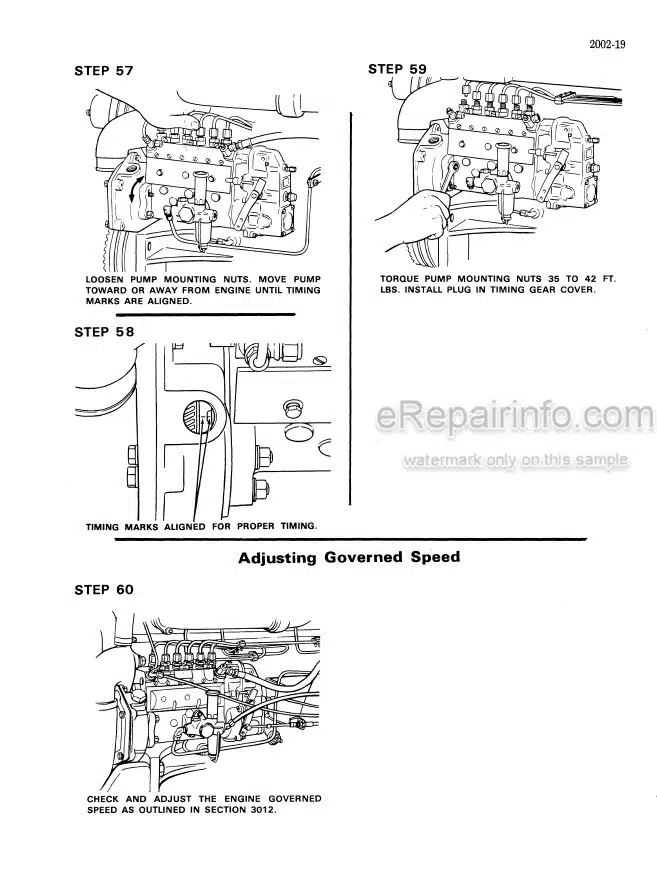
Adjusting Idle Speeds And Throttle Controls
-ELECTRICAL SYSTEM
Specifications
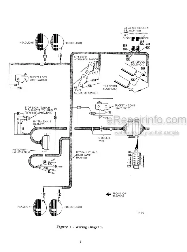
Wiring Diagram
Trouble Shooting Chart
Trouble Shooting The Starting Circuit
Batteries
Starter
Starter Solenoid
Solenoid Switch
Trouble Shooting The Charging Circuit
Servicing And Testing The Alternator
Alternator Belt Adjustment
Instrument Panel Resistor Checks
Checking Air Pressure Warning System
Neutral Start Switch Adjustment
Bucket Height Control Electrical Checkout
Return To Dig Electrical Checkout
-TRANSMISSION
Removal And Installation
Supplement (Powershift Transmission)
-DIFFERENTIALS AND PLANETARIES
Differential Trouble Shooting Chart
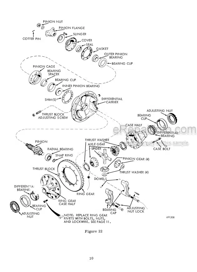
Differential
Planetary Trouble Shooting Chart
Planetaries
Driveshafts And Universal Joints
Front Driveshaft Center Bearing
-BRAKES AND AIR OPERATED CONTROLS AND ACCESSORIES
Pressurizing/Depressurizing The Air System
Operating Principles
Diagram Of Air And Brake System
Air Compressor
Governor
Treadle Valves
Brake Actuators
Foot Brakes
Parking Brake
Reservoirs
Safety Valve
Moisture Ejection Valve
Pressure Protection Valve
Air Regulator Valve
Double Check Valve
Clutch Cut-Out Valve
Air Horn And Air Horn Valve
-HYDRAULIC SYSTEM
Hydraulic Diagram – Without Demand Valve
Hydraulic Diagram – With Demand Valve
Hydraulic Specifications
Pressurizing/Depressurizing The Hydraulic Reservoir
Checking Pressure Setting Of Loader Main Relief Valve
Checking Pressure Setting Of Steering Relief Valves
Hydraulic Oil Drain/Refill And Reservoir Filter Service
Trouble Shooting Chart
Trouble Shooting With A Flowmeter
Testing Secondary Relief Valves With Hand Pump
Steering Control Valves
Demand Valve
Loader Cylinders (Inc Tilt And Lift Cyls)
Drott Bucket Cylinders
Steering Cylinders
-STEERING
Steering Hydraulic Specifications
Operating Principles
Steering Hydraulics Trouble Shooting Chart
Steering Relief Valve Pressure Check And Adjustment
Demand Valve
Steering Control Valve
Steering Cylinders
Steering Gear And Chassis Pivots
Steering Gear Linkage Adjustments
Steering Gear (Servicing)
Upper And Lower Chassis Pivots
-LOADER
Bucket Position Control (Return To Dig And Automatic Rollback) Description
Bucket Height Control Description
Bucket Height Control Adjustments
Bucket Height Control Parts Replacement
Automatic Bucket Rollback And Return To Dig Adjustments
Checking Return To Dig Electrical Components
Checking Bucket Height Control Electrical Components
Replacing Bucket Cutting Edges And Teeth
Servicing The DROTT Bucket
-MAINTENANCE AND LUBRICATION
Serial Number Locations
Lubrication And Maintenance Specifications
Fuel
Fuel Filter And Strainer Servicing
Dry Type Air Cleaner
Oil Bath Type Air Cleaner
Air Cleaner Restriction Indicator
Oil Filters Servicing
Belts Replacement And Adjustment
Thermostat Replacement
Torque Specifications
What you get
You will receive PDF file with high-quality manual on your email immediately after the payment.
Reviews
There are no reviews yet