Factory Workshop Manual For Fiat 855C, 955C, 85-55, 95-55 Tractor. Manual Contains Illustrations, Instructions, Diagrams For Step By Step Remove And Install, Assembly And Disassembly, Service, Inspection, Repair, Troubleshooting, Tune-Ups.
Format: PDF
Language: English
Pages: 204
Number: 06910092
Bookmarks: Yes
Wiring Diagrams: Yes
Hydraulic Diagrams: Yes
Model
Fiat Tractor
855C
955C
85-55
95-55
Contents
-GENERAL
General Instructions
Safety Precautions
-SPECIFICATION
Identification Data
Weights – Engine
Power Train – Undercarriage – Suspensions
Power Train Schematics – Speed – Remote Implement Control Hydraulic System -Hitch And Rockshaft Controls
Overall Dimensions – Towing Attachments – Ballasting – Body
Electrical System
Capacities
-ENGINE SPECIFICATION AND DATA
Engine Block – Cylinder Head
Crank Gear
Valve Gear
Lubrication System
Cooling System
Fuel System
Injection Pump Calibration Data
Tightening Torque Figures
-FIGURES
Longitudinal Section Through Engine
-ENGINE DESCRIPTION – PERFORMANCE DATA – REMOVAL -INSTALLATION
Description
Performance Data
Compression Test
Removal-Installation
-ENGINE ENGINE BLOCK – CYLINDER HEAD
Cylinder Sleeves
Cylinder Head
-ENGINE VALVEGEAR
Camshaft
Valves – Guides – Springs – Tappets -Pushrods – Rocker Arms
Valve Timing Gear Train
-ENGINE CRANKGEAR
Crankshaft
Main And Connecting Rod Bearings And Caps
Pistons And Rings
Connecting Rods
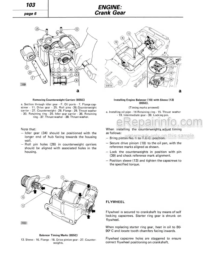
Dynamic Balancer (Model 855C)
Flywheel
-ENGINE FUEL SYSTEM
Air Cleaner – Fuel Tanks
Fuel Filters
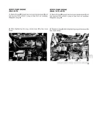
Internal Pump Timing – Bosch Distributor Pump (855C)
Internal Pump Timing – C A V Distributor Pump
Injection Pump Installation And External Timing – Bosch And C A V (855C)
Injection Pump Installation And External Timing – Bosch (955C)
-ENGINE LUBRICATION SYSTEM
Lubrication System Diagram
Oil Pump – Oil Filter – Low Oil Pressure Indicator System
-ENGINE COOLING SYSTEM
Cooling System Diagram
Description – Water Pump
Radiator
Belt Tension Adjustment
Water Temperature Gauge – Thermostat
-POWER TRAIN SPECIFICATION AND DATA CLUTCH
Transmission And Splitter
Bevel Drive
Steering Clutches
Brakes
Final Drives – Power Takeoff
Tightening Torque Figures
-POWER TRAIN-CLUTCH
Removal – Installation
Sections
Overhaul
Adjustment
Control Lever Adjustment
-POWER TRAIN TRANSMISSION AND SPLITTER
Longitudinal And Cross Sections
Removal – Installation
Disassembly
Inspection – Assembly
-POWER TRAIN BEVEL DRIVE
Adjustment
-POWER TRAIN STEERING CLUTCHES – BRAKES – FINAL DRIVES
Steering Clutches
Brakes
Final Drives
-POWER TRAIN POWER TAKEOFF
Sections
Description – Removal And Installation -Overhaul
-UNDERCARRIAGE SPECIFICATION AND DATA
Track Chains
Track Tension Mechanism – Front Idler -Track Rollers
Carrier Rollers – Track Frames And Suspensions
Tightening Torque Figures
-UNDERCARRIAGE TRACK CHAINS
Front Idler, Roller And Track Shoe Details
Disassembly And Assembly
Removal And Installation – Link Replacement
-UNDERCARRIAGE TRACK TENSION MECHANISM
Track Tension Mechanism
Adjustment
-UNDERCARRIAGE FRONT IDLER – TRACK AND CARRIER ROLLERS
Front Idler Overhaul And Adjustment
Track Roller Overhaul And Installation
Carrier Roller Overhaul
Track Roller And Front Idler Lubrication
-UNDERCARRIAGE TRACK FRAMES AND SUSPENSIONS
Track Frame Removal And Inspection
Track Frame Installation, Adjustment And Alignment
Front And Rear Suspensions
Section Through Track Frame Articulation – Suspension Beam And Section Through Track Frame Support
-HYDRAULIC TRACTOR IMPLEMENT CONTROL SYSTEM SPECIFICATION AND DATA
Hydraulic Pump
Remote Implement Control Valves
Rockshaft Controls
Hitch
Tightening Torque Figures
-HYDRAULIC TRACTOR IMPLEMENT CONTROL SYSTEM HYDRAULIC PUMP
Overhaul
Output Test
-HYDRAULIC TRACTOR IMPLEMENT CONTROL SYSTEM REMOTE IMPLEMENT CONTROL VALVES
Description, Operation And Diagrams
Sections, Relief Valve Adjustment, Spool Return Test, Leakage Test And Connection Schematics
-HYDRAULIC TRACTOR IMPLEMENT CONTROL SYSTEM ROCKSHAFT CONTROLS
Description
-HYDRAULIC TRACTOR IMPLEMENT CONTROL SYSTEM HITCH AND DRAWBAR
Description And View
-ELECTRICAL SYSTEM SPECIFICATION AND DATA
Charging System
Starter
Battery – Fuses – Lighting – Indicators
Accessories
Starter Switch And Lighting Switch
Turn Signal Switch
Instrument Panel And Control Board
Wiring Diagram
-SERVICE TOOLS
What you get
You will receive PDF file with high-quality manual on your email immediately after the payment.




Reviews
There are no reviews yet