Factory Service Manual For Gehl All Wheel Steer Loader. Manual Contains Illustrations, Instructions, Diagrams For Step By Step Remove And Install, Assembly And Disassembly, Service, Inspection, Repair, Troubleshooting, Tune-Ups.
Format: PDF
Language: English
Pages: 172
Number: 918114
Searchable: Yes
Wiring Diagrams: Yes
Hydraulic Diagrams: Yes
Model
Gehl All Wheel Steer Loader
280
Contents
-SPECIFICATIONS
Type Decals And Component Numbers
Machine Overview
Cab Overview
Instrument Panel, Multifunctional Lever And Drive Lever
Machine Specifications
-MAINTENANCE
Fluids And Lubricants
Explanation Of Symbols For The Maintenance Decal
Maintenance Schedule (Overview)
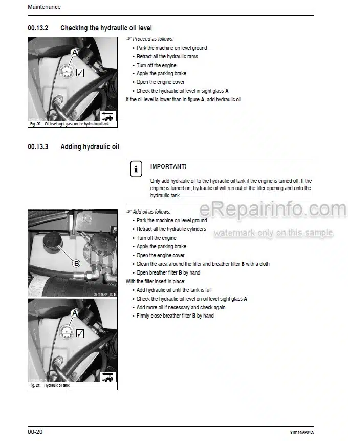
Maintenance Items
Refueling
Fuel Prefilter (Water Separator)
Cleaning The Fuel Filter
Bleeding The Fuel System
Engine Lubrication System
Checking/Filling Up The Coolant Level
Air Filter
V-Belt
Hydraulic System
Gearboxes And Axles
Loader Unit
Tire Care
Tire Care
Electrical System
General Maintenance Work
-ENGINE
Specifications
Engine Overview (Front Driving Direction)
Engine Overview (Rear Driving Direction)
Fuel Injection System
Fuel Injection Nozzle
Engine Valve Tip Clearance
Engine Cooling: Overview
Fuel System: Overview
Engine Trouble
-POWER TRAIN
Description: Variable Displacement Pump A 10 VG 28 Da
Description: Hydraulic Motor VM 45 EZ 6
Fuel System: Overview
Measuring Points: Variable Displacement Pump
Overview: Hydraulic Motor
Diagram: Hydraulic Speed Range
Check And Adjustment Instructions
-AXLES
Type Decal – Axle
Drain, Fill And Check Plug
Tightening Values Lb-Ft (NM)
Screw Connections
Sealing Work
-BRAKES
Overview: Brake System
Readjustment: Parking Brake
Basic Setting: Cables
-STEERING
Overview – Steering Circuit
Steering Diagram
Hydraulic Circuit: Steered To The Left
Hydraulic Circuit: Steered To The Right
Hydraulic Ports On Servostat
Adjustment: Pressure Relief Valve – Servostat
Sealing Steering Cylinders
Adjustment: Pressure Relief Valve – Servostat
Sealing Steering Cylinders
-ELECTRICAL SYSTEM
Ohm’s Law (Current, Voltage, Resistance); Power
Measuring Equipment, Measuring Methods
Terminal Description
Cable Color Coding
Relays
Three-Phase Alternator, Starter
Battery
Fuse Box In Control Lever Base
Main Fuse Box With Relays In The Engine Compartment
Overview: Board
Plug And Socket Connection: Wiring Harness
Wiring Harness 207404
Cab – Wiring Harness 207412
Roof – Wiring Harness 209336
Roof – Wiring Harness 207414
Wiring Diagram 207406
Cable Colors: Steering-Column Control Lever S2 And S3 To Plugs 101, 102 And X9
Cable Routing From Steering-Column Control Lever S3 On Left, Starting Plug X9
Cable Routing From Steering-Column Control Lever S2 On Right, Starting Plug 101
Cable Routing From Steering-Column Control Lever S2 On Right, Starting Plug 102
-HYDRAULICS
Hydraulics Diagram – Pilot Control
Hydraulics Diagram – Float Position
Hydraulic Circuit: Pump – Control Valve – Tank
Overview: Control Valve
Hydraulic Ports On Control Valve
Hydraulic Circuit Pilot Control
Sealing The Lift Cylinder
Sealing The Tilt Cylinder
Sealing The Quickhitch Cylinder
Overview: Loader Unit
Hydraulic Circuit 4Th Control Circuit
Hydraulics Diagram: 4Th Control Circuit – Solenoid Valve No Contact (Neutral Circulation)
Hydraulics Diagram: 4Th Control Circuit – Solenoid Valve With Contact
Hydraulics Diagram: 3Rd + 4Th Control Circuit – Solenoid Valve With Contact
Test And Setting Instructions For Work Hydraulics
Legend For Hydraulics Diagram
-HEATING
Heating Circuit: Overview
What you get
You will receive PDF file with high-quality manual on your email immediately after the payment.




Reviews
There are no reviews yet