Factory Technical Manual and Workshop Manual For Hitachi EX200-2 Excavators. Tons of illustrations, instructions, diagrams for step by step remove and install, assembly and disassembly, service, inspection, repair, troubleshooting, tune-ups.
Format: PDF
Language: English
Pages: 843
Bookmarks: Yes
Searchable: No
Wiring Diagrams: Yes
Hydraulic Diagrams: Yes
Model
Hitachi EX200-2
Contents
1.Technical Manual
INTRODUCTION
SAFETY
-SPECIFICATIONS
–GENERAL INFORMATION
Foreword
Specifications
Working Range
Lifting Capacities
Service Refill Capacities
–DIMENSIONS AND WEIGHTS
Transportation
Weights
–FUELS AND LUBRICANTS
Fuel
Grease
Engine Oil
Gear OU
Hydraulic Oil
Engine Coolant
–INTERCHANGEABILITY
Interchangeability
Installation of Attachments
-UPPERSTRUCTURE
–LAYOUT
Layout of Upperstructure
–TANKS
Construction and Function
Hydraulic Oil Tank
Fuel Tank
–PUMP DEVICE
Construction and Function
Main Pump
Regulator
Gear Pump
–SWING DEVICES
Construction and Function
Swing Motor
Brake Valve
Parking Brake
Swing Dampener Valve
Swing Reduction Device
–PIPINGS
Construction and Function
Main pipings
Pilot pipings
–CONTROL VALVE
Construction
No1 Valve (Three spools side)
No2 Valve (Four spools side) System Pressure Regulator
Surge Relief Valve
Overload Relief Valve with Anti-Cavitation Feature
Variable Pressure Compensated
Valve
Shuttle Valve
Holding Valve
Operation (Lever m Neutral)
Operation(Single)
Operation(Combined)
Hydraulic Pilot Warm Up Circuit
Auxiliary Spool Speed Adjustment
–PILOT VALVE
Construction and Function
Pilot Valve
Shuttle Valve
–LOCK VALVE
Construction and Function
— SHOCKLESS VALVE
Construction and Function
— ACCUMULATOR
Construction
Function
Cautions for Handling
–SOLENOID VALVE
Construction and Function
Pump Displacement Solenoid Valve
Solenoid Valve Assembly
-UNDERCARIAGE
–COMPONENT LOCATION
Component Location
–SWING BEARING
Construction and Operation
–CENTER JOINT
Construction and Operation
–TRAVEI DEVICE
Construction and Operation
Travel Reduction Device
Travel Motor
Travel Brake Valve
Parking Brake
–ADJUSTER
Construction and Operation
-ELECTRICAL SYSTEM
–COMPONENT LOCATION
Component Location
Monitor and Switch Panel
Monitor Panel
Switch Panel (1)
Switch Panel (2)
Relays
Electric Wiring Diagram
Connector
–ENGINE CONTROL SYSTEM
Outline of the Control System
Summary of Control Circuits
Outline of the Engine Control System
Operation of the Engine Control Motor
Engine Control Circuit
Setting Engine Mode Speeds and Engine Speed Programing
Engine Stop Double Function
Function of the Main Electrical Equipment
–MONITOR
Outline of the Monitor
Monitor Panel
Monitor Function
Monitor Check Procedure
–CIRCUIT OPERATION
Characteristics of the Electrical System
Power Circuit
Preheat Circuit
Engine Start Circuit
Changing Circuit
Operation of the Regulator
Voltage Adjustment
How to Trouble Shoot Malfunction in the Circuit
Surge Voltage Prevention Circuit Accessory Circuit
EC Motor Engine Stop
Stop Motor Engine Stop
Key Switch Engine Stop
Emergency Engine Stop
Auto Idle Function
–INSPECTION AND MAINTENANCE
Precautions for Inspection and Maintenance
Fuse Continuity Test
Taking Apart Connector
Inspection and Replacement of Fusible Link
Installation and Adjustment of the A – Sensor
Positioning the EC Sensor
-HYDRAULIC SYSTEM
–GENERAL
General
Main Circuit
Suction Circuit
Delivery Circuit
Return Circuit
Drain Circuit T
System Pressure Regulate Control
Pilot Circuit
Suction Circuit
Delivery Circuit
Return Circuit
Control System
Control System Layout
–CONTROL SYSTEM
Pump Control System
Load Sensing System
Speed Sensing System
Valvo Control System
Flow Dividing Control System
Job Mode Selector
Propel Speed Control System
3-Speed Propel Control
Other Control System
Swing Parking Brake
Warming-Up Control
Power Boost System
–MAIN HYDRAULIC CIRCUIT
Neutral Circuit
Swing Operation
Arm In Circuit
Swing Circuit
Combined Operation
Combined Boom and Swing Circuit
Relief Circuit
-OPERATIONAL PERFORMANCE TEST
–STANDARD
Operational Performance Standard
–INTRODUCTION
Purpose
Terminology
Preparation For Performance Tests
–ENGINE TEST
Engine Speed
Engine Compression Pressure
–EXCAVATOR TEST
Travel Speed
Track Revolution Speed
Mistrack
Travel Parking Function Check
Swing Speed
Swing Function Drift Check
Swing Motor Leakage
Swing Bearing Play
Hydraulic Cylinder Cycle Time
Dig Function Drift Check
Control Lever Operating Force
Control Lever Stroke
Combined Boom Raise/Arm Roll-In Functions Check
Combined Boom Raise/Swing Functions Check
–HYDRAULIC COMPONENT TEST
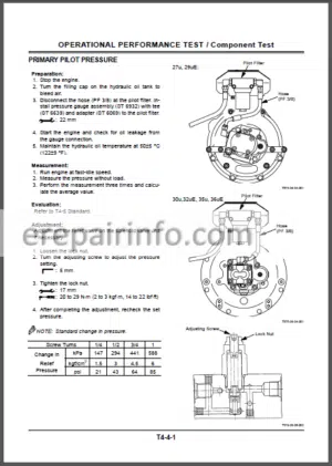
Pilot Primary Pressure
Adjustment
Pilot Secondary Pressure
Proportional Solenoid Valve Pressure (PC Pressure)
Adjustment
Swing Parking Brake Releasing Pressure
Reducing Valve Pressure Setting (Pl Pressure)
Adjustment
Main Pump Delivere Pressure
System Pressure Regulator Relief Setting
Adjustment
Overload Relief Valve Pressure Setting
Adjustment
Main Pump Flow Test
(Reference) Pump PQ CurveT
Swing Motor Drainage
Travel Motor Drainage
–BASIC PERFORMANCE CHECK
Basic Performance Check
With the Dr EX
Pressure (P) switch
ln the Neutral Position, and at Relief Pressure
A sensor ( Pump Displacement Angle Sensor)
Single Operation
Combined Operation
Combinod Boom raise and Arm roll-in
Combinod Bucket roll-in relief and Boom raise
Combined Bucket roll-in and Boom raise
Combined Travel and Arm roll-in relief
Swing Check with Precision mode (M4)
-TROUBLESHOOTING
–DIAGNOSING PROCEDURE
Introduction
Diagnosing Procedure
Start-Up Procedure of DrEX
Self-diagnosis Function
Clearing Self-Diagnosis Function DrEX Monitor Function
Check Battery Voltage and Fuses
Check Fusible Link
–CONNECTOR
Connector Location
Types of Each Connector
–TROUBLESHOOTING A
List of EC-Related Fault Codes List of PVC-Related Fault Codes
Fault Codes 01,0203,04 and 06
Fault Code 05
Fault Codes 09 and 10
Fault Code 13
Fault Codes 17,18,19 and 21
Fault Code 20
Fault Code 22
Fault Codos 25 and 26
Fault Codes 27 and 28
Fault Codes 29 and 30
Fault Codes 31 and 32
–TROUBLESHOOTING B
Outline
Effect of Electronic Component Malfunctions on Machine Operations
Machine Malfunctions and Possible Causes
DrEX monitoring Items and Reference Values
Engine
Actuators
Front Attachments
Swing
Travel
Others
–TROUBLESHOOING C
Monitor Panel, Switch and Sensor Location
Malfunction of Coolant
Temperature Gauge
Malfunction of Fuel Gauge
Malfunction of Level Check Switch
Malfunction of Engine Oil Level Indicator
Malfunction of Coolant Level Indicator
Malfunction of Hydraulic Oil Level Indicator
Malfunction of Alternator Indicator
Malfunction of Engine Oil Pressure Indicator
Malfunction of Overheat Indicator
Malfunction of Fuel Level Indicator
Malfunction of A»r Filter Restriction Indicator
Malfunction of Buzzer
Malfunction of Hour Meter
–HARNESS CHECK
Wiring Harness Test
Test 1 Battery Circuit Test
Test 2 5 Volt Sensor Circuit Test
Test 3 Branchless Harness Test
Test 4 Test Harnesses Between Switch Panel 2 and PVC/EC
Test 5 T sensor Harness Test
Test 6 Pressure Switch Harness Test
Test 7 Proportional Solenoid Valve Hamess Test
Test 8 Pump Displacement Solenoid Valve Harness Test
Test 9 Swing Dampener Solenoid Valve Harness Test
Test 10 Directional Solenoid Valve Harness Test
Test 11 EC motor Harness Test Test 12 Engine Stop Motor Harness Test
Test 13 Emergency Relay Activation Test
Test 14 Relay Circuit Test
2.Workshop Manual
-SPECIFICATIONS
–TIGHTENING TORQUE
Tightening Torque
Specification
–PAINTING STANDARD
Painting Standard
-UPPERSTRUCTURE
–CAB
Removal and Installation
–COUNTER WEIGHT
Removal and Installation
–MAIN FRAME
Removal and Installation
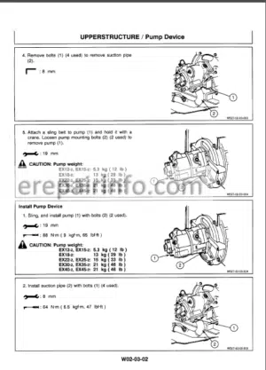
–PUMP DEVICE
Removal and Installation of Pump Device
Disassembly of Pump Device
Assembly of Pump Device
–CONTROL VALVE
Removal and Installation
Disassembly of Four Section Control Valve
Assembly of Four Section Control Valve
Disassembly of Three Section Control Valve
Assembly of Three Section Control Valve
–SWING DEVICE
Removal and Installation of Swing Device
Disassembly of Swing Device Assembly of Swing Device
Removal and Installation of Swing Motor
Disassembly of Swing Motor
Assembly of Swing Motor
Maintenance Standard
–PILOT VALVE
Removal and Installation of Pilot Valve for front
Disassembly of Pilot Valve for front
Assembly of Pilot Valve for front
Removal and Installation of Pilot Valve for Traveling
Disassembly of Pilot Valve for Traveling
Assembly of Pilot Valve for Traveling
Maintenance Standard
–SHUT-OFF VALVE
Removal and Installation
Disassembly
Assembly
–SHOCKLESS VALVE
Removal and Installation
Disassembly
Assembly
–ACCUMULATOR
Removal and Installation
–SOLENOID VALVE
Removal and Installation
Disassembly of Solenoid Valve
Assembly of Solenoid Valve
Disassembly of Propotional Solenoid Valve
Assembly of Propotional Solenoid Valve
Disassembly ol Relife Valve
Assembly of Relile Valve
disassembly of Reducing Valve
Assembly of Reducing Valve
–SHUTTLE VALVE
Removal arid Installation of Travel shuttle valve
Disassembly and Assembly of Travel shuttle valve
Removal and Installation of
Swing / Bucket shuttle valve
Disassembly and Assembly of Swing / Bucket shuttle valve
–SWING DAMPENER VALVE
Removal and Installation
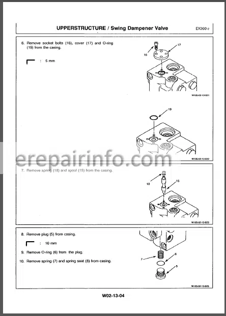
Disassembly of Swing Dampener valve
Assembly of Swing Dampener valve
Disassembly of valve
Assembly of valve
-UNDERCARRIAGE
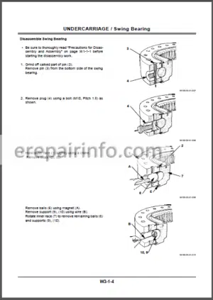
–SWING BEARING
Removal and Installation
Disassembly
Assembly
Maintenance Standard
–TRAVEL DEVICE
Removal and Installation of Travel Device
Disassembly of Travel Device Assembly of of Travel Device
Removal and Installation of Travel Motor
Disassembly of Travel Motor
Assembly of of Travel Motor
Disassembly of Brake Valve
Assembly of of Brake Valve
Maintenance Standard
–CENTER JOINT
Removal and Installation
Disassembly
Assembly
Maintenance Standard
–TRACK ADJUSTER
Removal and Installation
Disassembly
Assembly
–FRONT IDLER
Removal and Installation
Disassembly
Assembly
Maintenance Standard
–UPPER AND LOWER ROLLER
Removal and Installation of Upper Roller
Removal and Installation of Lower Roller
Disassembly of Upper Roller
Assembly of Upper Roller
Disassembly of Lower Roller
Assembly of Lower Roller
Maintenance Standard
–TRACK LINK
Track Link
Removal
Installation
Maintenance Standard
What you get
You will receive PDF file with high-quality manual on your email immediately after the payment.




Anonymous (verified owner) –
Awesome