Factory Service Technical Manuals (Operational Principle, Troubleshooting) For Hitachi ZX 70-3 70LC-3 70LCN-3 75US-3 85US-3 Excavators. Tons of illustrations, instructions, diagrams for step by step remove and install, assembly and disassembly, service, inspection, repair, troubleshooting, tune-ups.
Format: PDF
Language: English
Pages: 638
Bookmarks: Yes
Searchable: Yes
Number: TO1P1-E-00
Wiring Diagrams: Yes
Hydraulic Diagrams: Yes
Model
Hitachi ZX 70-3, 70LC-3, 70LCN-3, 75US-3, 85US-3
Contents
1.Technical Manual(Operational Principle)
2.Technical Manual(Trobleshooting)
1.Technical Manual(Operational Principle)
-GENERAL
–SPECIFICATIONS
Specifications (Standard)
Working Ranges (Standard)
Specifications (EU)
Working Ranges (EU)
–COMPONENT LAYOUT
Mam Component Layout
Electrical System (Overview)
Electrical System (Monitor Switches)
Electrical System (Controllers Relays)
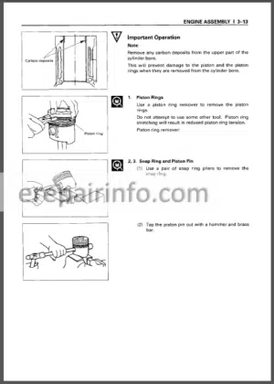
Engine
Electrical System (Pump Device)
Electrical System (Battery)
Control Valve
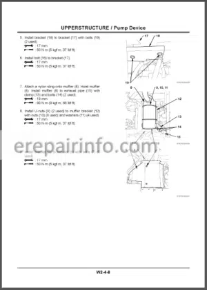
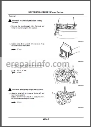
Pump Device
Swing Device
Travel Device
–COMPONENT SPECIFICATIONS
Engine
Engine Accessories
Hydraulic Component
Filter
Electrical Component
-SYSTEM
–CONTROLLER
Outline
CAN: Controller Area Network (Network Provided for Machine)
MC: Main Controller
ICF: Information Controller
Monitor Unit
–CONTROL SYSTEM
Outline
Engine Control
Pump Control
Valve Control
Other Control
–HYDRAULIC SYSTEM
Outline
Pilot Circuit
Main Circuit
–ELECTRICAL SYSTEM
Outline
Main Circuit
Electric Power Circuit (Key Switch: OFF)
Accessory Circuit
Preheating Circuit
Starting Circuit (Key Switch: START)
Charging Circuit (Key Switch: ON)
Serge Voltage Prevention Circuit
Pilot Shut-Off Circuit (Key Switch: ON)
Security Lock Circuit
EGR (Exhaust Gas Recirculation) Control
Engine Stop Circuit (Key Switch OFF)
Security Horn Circuit
Working Light Circuit
Wiper / Washer Circuit
-COMPONENT OPERATION
–PUMP DEVICE
Outline
Main Pumps 1 2 and 3
Regulator of Main Pumps 1 and 2
Regulator of Main Pump 3
Pilot Pump
N Sensor (Engine Speed Sensor)
–SWING DEVICE
Outline
Swing Motor
Swing Parking Brake
Make-Up Valve
Relief Valve
Swing Reduction Gear
–CONTROL VALVE
Outline
Hydraulic Circuit
Flow Combiner Valve
Mam Relief Pressure Selection
Boom Anti-Dnft Valve
Main Relief Valve
Overload Relief Valve
–PILOT VALVE
Outline
Operation
Shockless Function (Only for Travel Pilot Valve)
–TRAVEL DEVICE
Outline
Travel Motor
Parking Brake
Travel Brake Valve
Travel Reduction Gear
–OTHERS (UPPERSTRUCTURE)
Pilot Shut-Off Solenoid Valve
Shockless Valve
2-Spool Solenoid Valve Unit
EC Motor
Pilot Relief Valve
Engine Fan Clutch
–OTHERS (UNDERCARRIAGE)
Swing Bearing
Center Joint
Track Adjuster
2.Technical Manual(Troubleshooting)
-OPERATIONAL PERFORMANCE TEST
–INTRODUCTION
Operational Performance Tests
Preparation for Performance Tests
–STANDARD
Operational Performance Standard Table
Mam Pump 1, 2 P-Q Diagram (ZX70-3)
Main Pump 1, 2 P-Q Diagram (ZX75US-3)
Mam Pump 3 P-Q Diagram
Sensor Activating Range
–ENGINE TEST
Engine Speed
Engine Compression Pressure
Valve Clearance
Nozzle Check
Injection Timing
Lubricant Consumption
–EXCAVATOR TEST
Travel Speed
Track Revolution Speed
Mistrack Check
Travel Parking Leakage
Swing Speed
Swing Function Drift Check
Swing Motor Leakage
Maximum Swingable Slant Angle
Swing Bearing Play
Hydraulic Cylinder Cycle Time
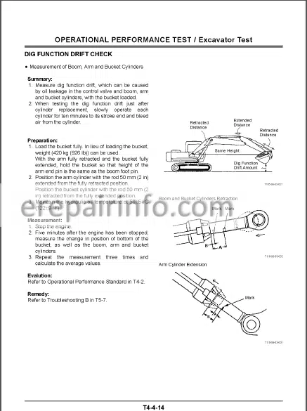
Dig Function Drift Check
Control Lever Operating Force Control Lever Stroke
Combined Operation of Boom Raise / Swing Function Check
–COMPONENT TEST
Primary Pilot Pressure
Secondary Pilot Pressure
Solenoid Valve Set Pressure
Mam Pump Delivery Pressure
Main Relief Set Pressure
Overload Relief Valve Set Pressure
Main Pump 1 and 2 Flow Rate
Main Pump 3 Flow Rate
Swing Motor Drainage
Travel Motor Drainage
–ADJUSTMENT
Engine Speed Adjustment and Engine Learning
Guveiriui Level and Fuel Cut Lever Positions
-TROUBLESHOOTING
–DIAGNOSING PROCEDURE
Introduction
Diagnosing Procedure
–MONITOR UNIT
Outline
Howto Use Screens
Screen Display When an Alarm is Issued
Contents of Alarms
Time Setting
Maintenance Setting
Mail (Optional)
Password Change (Optional)
Back Monitor Setting
Language Setting
Monitoring
Service Menu (Built-In Diagnosing System) Operation
Troubleshooting
Monitoring
Controller Version
Keyless Hour Meter
List of Monitor Unit Sotting Function
–DR ZX
Outline
Monitoring List
MC Setup
All Parameter Initialize
ICF Setup
Dr ZX Operation Procedure
–ICF
Outline
List of Daily Report Data
List of Frequency Distribution Data
List of Total Operating Hours
How to Download and Upload Data of ICF
Various Setup of ICF and Satellite Communication Terminal by Using Dr ZX
List of Fault Code
Satellite Communication System
–COMPONENT LAYOUT
Main Component Layout
Electrical System (Overview)
Electrical System (Monitor, Switches)
Electrical System (Controllers, Relays)
Engine
Electrical System (Pump Device)
Electrical System (Battery)
Control Valve
Pump Device
Swing Device
Travel Device
Components in Control Valve
–TROUBLESHOOTING A
Troubleshooting A Procedure
MC Fault Code List
ECF Fault Code List
ICF Fault Code List
Satellite Terminal Fault Code List
Monitor Unit Fault Code List
MC Fault Codes 11000 to 11002
MC Fault Code 11003
MC Fault Code 11004
CAN Harness Check
MC Fault Code 11100
MC Fault Code 11101
MC Fault Cede 11304
MC Fault Code 11307
MC Fault Code 11401
MC Fault Code 11405
MC Fault Codes 11910 to 11920
MC Fault Code 11901
ICF Fault Codes 14000 to 14003
Information C/U: Initialize
Control Data: Initialize
Enter Model and Serial No
ICF Fault Codes 14006, 14008
Satellite Terminal Fault Codes 14100 to 14106
Monitor Unit Fault Code 13303
Monitor Unit Fault Code 13304
Monitor Unit Fault Codes 13306 and 13308
Monitor Unit Fault Code 13310
Monitor Unit Fault Code 13311 Pilot Shut-Off Lever Alarm
–TROUBLESHOOTING B
Troubleshooting B Procedure
Relationship between Machine Trouble Symptoms and Related Parts
Correlation between Trouble Symptoms and Part Failures
Engine System Troubleshooting
All Actuator System Troubleshooting
Front Attachment System Troubleshooting
Swing System Troubleshooting
Travel System Troubleshooting
Blade System Troubleshooting
Other System Troubleshooting
Exchange Inspection
Emergency Boom Lowering Procedure
–ELECTRICAL SYSTEM INSPECTION
Precautions for Inspection and Maintenance
Instructions for Disconnecting Connectors
Fuse Inspection
Fusible Link Inspection
Battery Voltage Check
How to Check Alternator
Continuity Check
Voltage and Current Measurement
Check by False Signal
Test Harness
What you get
You will receive PDF file with high-quality manual on your email immediately after the payment.




Reviews
There are no reviews yet