Factory Service Manual For International Tractor Chassis. Manual Contains Illustrations, Instructions, Diagrams For Step By Step Remove And Install, Assembly And Disassembly, Service, Inspection, Repair, Troubleshooting, Tune-Ups.
Format: PDF
Language: English
Pages: 603
Number: GSS14703R0
Bookmarks: Yes
Searchable: Yes
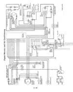
Wiring Diagrams: Yes
Hydraulic Diagrams: Yes
Model
International Chassis for Tractor
786
886
986
1086
1486
1586
Hydro 186
Contents
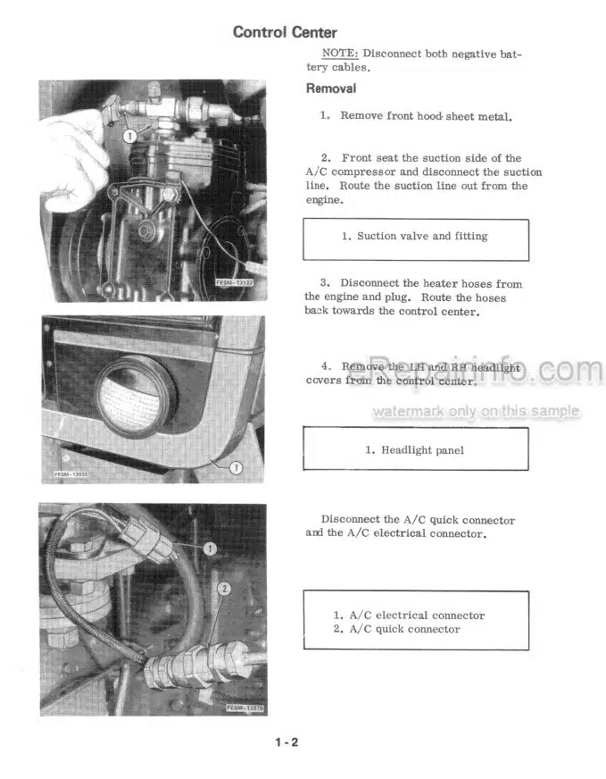
-CONTROL CENTER, A/C AND TRACTOR SPLITS
Control CENTER
Air Conditioning System
Air Conditioning Components
Windshield Wiper Motor
Recirculation Door And Adjustment Rod Removal
Split Between The Engine And Speed Transmission
Rear Split — Control Center On The Rear Frame
Rear Split – Control Center On The Speed Transmission (Includes Splitting The Axle Housings}
Rear Split – Control Center On The Speed Transmission (Without Splitting The Axle Housings)
Tractor Ballast
-FONT END, AXLE AND WHEELS
Adjustable Wide Front Axle
Special Torques
Front Axle Service
Steering Arm Adjustment
Adjusting Toe-In
Tricycle Front Axle
All Wheel Drive Tractors with Internal Steering Cylinder
Specifications
Description
Wheel Ends
Adjusting Steering Stops and Toe-In
Differential
All Wheel Drive Tractors with
External Steering Cylinders
Wheel Ends
Adjusting Steering Stops and Toe-In
Differential
Gear Box for Internal Steering Cylinder Front Axle
Drive Line for Internal Steering Cylinder Front Axle
Gear Box for External Steering Cylinder Front Axle
One Piece Drive Line for External Steering Cylinder Front Axle
Two Piece Drive Line for External Steering Cylinder Front Axle
-STEERING
SPECIFICATIONS
POWER STEERING
General
Principles of Operation
Steering Wheel and Shaft
Steering Shaft Housing
Steering Hand Pump
Power Steering Cylinder (External)
Power Steering Cylinder (Cylinder in upper bolster)
-ENGINE
Engine Removal and Installation
-FUEL SYSTEM
Main Fuel Tank
Auxiliary Fuel Tank
-ELECTRICAL SYSTEM
Specifications
Digital Monitor
Digital Data Center
Retro-Fit Data Center
Transducer
-COOLING SYSTEM
Removal
Reassembly
-CLUTCH AND FLY WHEEL
Clutch Specifications
Clutch Assembly
Clutch Booster Assembly
Clutch Linkage Adjustment
TA Spool Adjustment
Neutral Starting Switch Adjustment
-TRANSMISSION
Special Torques
Power Flow Gear Drive
Speed Transmission
Clutch Housing Repair Procedure
Torque Amplifier
Speed Transmission
IPTO Drive Shaft
Range Transmission
Park Lock Overhaul
Park Lock Linkage Adjustment
Range Shift Linkage Adjustment
Speed Shift Linkage Adjustment
Adjustments (Hydrostatic)
Directional Control Cable “A”
Speed Ratio Control Cable “B”
Servo Linkage Adjustment
Servo Control Adjustment
Foot Inch Valve Adjustment
Understanding the Lube Warning Light at Low Idle
-DIFFERENTIAL
Special Torques
Pinion Mounting Distance Set Up
Adjusting Bearings
Adjusting Backlash
Differential Lock
-REAR AXLE, HOUSING AND WHEELS
Special Torques
Rear Axle and Bull Pinion Shaft
High Clear Drop Housing
Rear Axle and Differential Assembly
-BRAKES
Specifications
Power Hydraulic Multi Disc Brakes
Brake Service (Bull Gear Drive Tractors)
Bleeding the Brakes
Power Hydraulic Brakes (Planetary Drive Tractor)
Brake Service (Planetary Drive Tractor)
Bleeding the Brakes
Power Brake Valve
Brake Pedal and Linkage Adjustment
-INDEPENDENT POWER TAKE OFF
Specifications
IPTO Assembly Drawings
IPTO Introduction
Removing the IPTO from the Tractor
Servicing IPTO Components
Installing the IPTO on the Tractor
IPTO Control Valve (IPTO W/O Hydraulic Anti Creep Brake) IPTO Control Valve (IPTO W/Hydraulic Anti Creep Pistons)
Control Handle and Linkage Adjustment (All Models)
Rear Linkage Adjustment (IPTO W/O Hydraulic Anti-Creep Brake)
Rear Linkage Adjustment (IPTO W/Hydraulic Anti-Creep Pistons)
Adjusting IPTO Pressure (IPTO W/O Hydraulic Anti-Creep Brake)
Adjusting IPTO Pressure (IPTO W/Hydraulic Anti-Creep Pistons)
-HYDRAULIC SYSTEM
Basic Hydraulic System
Open Center Load and Position Control Hitch and Auxiliary Hydraulic System
Closed Center Power Priority (PPH) Load and Position Control
Multiple Control Valve (MCV) (Basic Hydraulic System)
Multiple Control Valve Pumps
Power Priority Hitch Pump (PPH – Closed Center System)
Unloading Valve Assembly (Open Center System)
Motor Priority Valve (PPH – Closed Center System)
Auxiliary Valve Service
Flow Control Valve (PPH – Closed Center System)
Alternating Check Valve
Hydraulic Seat
Recharging Hydraulic Seat Accumulator
Coupler Service
Sump Check Valve Seat Service
Servicing the Rear Frame Cover and Hitch Components
Servicing, Torsion Bar, Crankarm Shaft Retainer and Bushings
Hydraulic Clean-Up Procedures
Procedures to Manufacture Dummy Filter By-Pass Valve
Hydraulic Fluid Level in Rear Frame
Checks and Adjustments
-TESTING AND HYDRAULIC SYSTEM
Specifications
Test No. 1 (PPH – Closed Center System)
Test No. 2 (PPH — Closed Center System)
Hydraulic System Analyzer (14-557) Installation (PPH – Closed Center System)
Test No. 3 (PPH — Closed Center System)
Test No. 4 (PPH – Closed Center System)
Test No. 5 (PPH – Closed Center System)
Test No. 8 (PPH – Closed Center System)
Test No. 9 (Basic Hydraulic System)
Test No. 10 (Basic Hydraulic System)
Test No. 11 (Basic Hydraulic System)
Test No. 12 (Basic Hydraulic System – Except H186)
Test No. 13 (Open Center System)
Test No. 14 (Open Center System)
Test No. 15 (Closed Center System)
What you get
You will receive PDF file with high-quality manual on your email immediately after the payment.



Reviews
There are no reviews yet