Factory Service Manual For JLG Telehandler. Manual Contains Illustrations, Instructions, Diagrams For Step By Step Remove And Install, Assembly And Disassembly, Service, Inspection, Repair, Troubleshooting, Tune-Ups.
Format: PDF
Language: English
Pages: 274
Number: 31200926 (january 2018)
Bookmarks: Yes
Searchable: Yes
Wiring Diagrams: Yes
Hydraulic Diagrams: Yes
Model
JLG Telehandler
G5-18A
2505H
Agrovector 25.5
SN 0160053000 to Present including 0160051045, 0160051047, 0160051049, 0160051194 & 0160051359
Contents
-SAFETY PRACTICES
Introduction
Disclaimer
Operation & Safety Manual
Do Not Operate Tags
Safety Information
Safety Instructions
Safety Decals
-GENERAL INFORMATION AND SPECIFICATIONS
Replacement Parts and Warranty Information
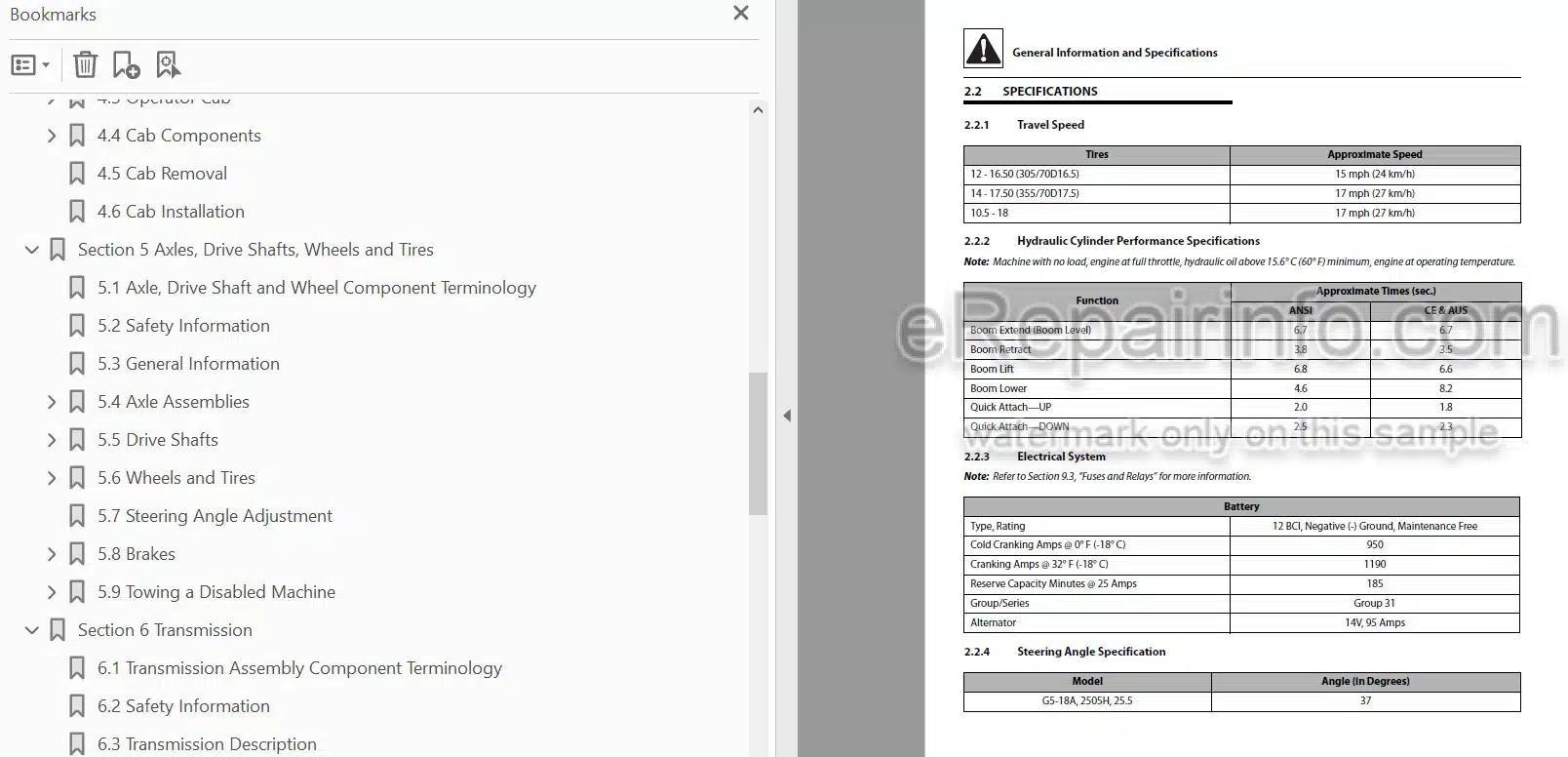
Specifications
Fluids, Lubricants and Capacities
Maintenance Schedule
Lubrication Schedule
Thread Locking Compound
Torque Charts
Hydraulic Connection Assembly and Torque Specification
-BOOM
Boom System Component Terminology
Safety Information
Two Section Boom System
Boom Assembly Maintenance
Boom Wear Pads
Quick Attach Assembly
Forks
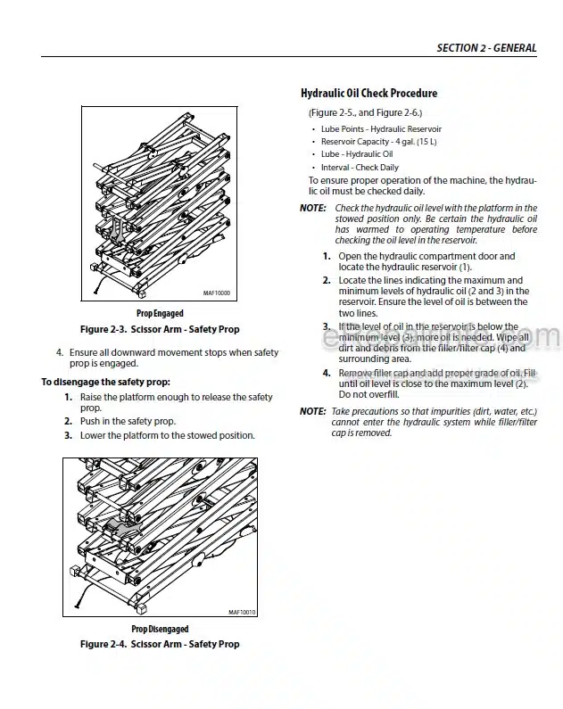
Boom Prop (if equipped)
Emergency Boom Lowering Procedure
Troubleshooting
-CAB
Operator Cab Component Terminology
Safety Information
Operator Cab
Cab Components
Cab Removal
Cab Installation
-AXLES, DRIVE SHAFTS, WHEELS AND TIRES
Axle, Drive Shaft and Wheel Component Terminology
Safety Information
General Information
Axle Assemblies
Drive Shafts
Wheels and Tires
Steering Angle Adjustment
Brakes
Towing a Disabled Machine
-TRANSMISSION
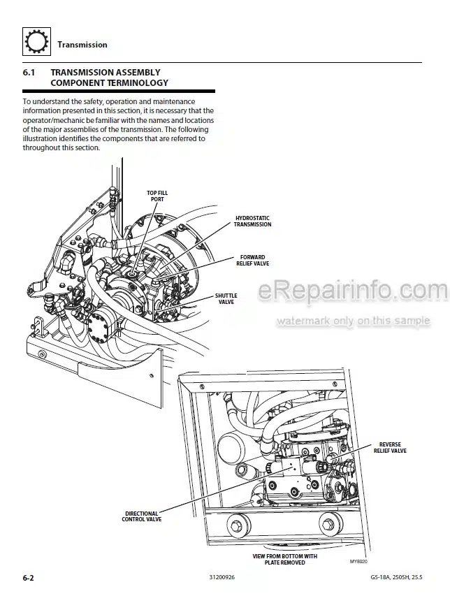
Transmission Assembly Component Terminology
Safety Information
Transmission Description
Transmission Specifications
Transmission Replacement
-ENGINE
Introduction
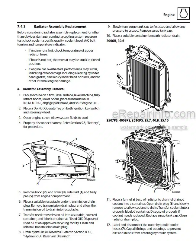
Engine Cooling System
Engine Electrical System
Fuel System
Engine Exhaust System
Air Cleaner Assembly
Engine Replacement
-HYDRAULIC SYSTEM
Hydraulic Component Terminology
Safety Information
General Information
Specifications
Hoses, Tube Lines, Fittings, Etc.
Hydraulic Pressure Diagnosis
Hydraulic Schematic
Hydraulic Reservoir
Hydraulic System Pump
Front Drive Motor
Control Valves
Hydraulic Cylinders
-ELECTRICAL SYSTEM
Electrical Component Terminology
Safety Information
Fuses and Relays
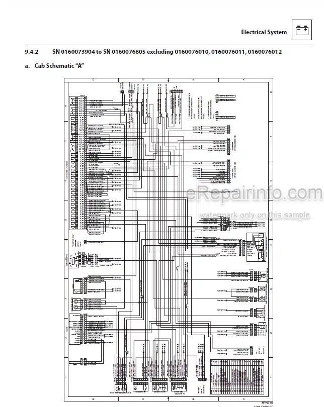
Electrical System Schematics
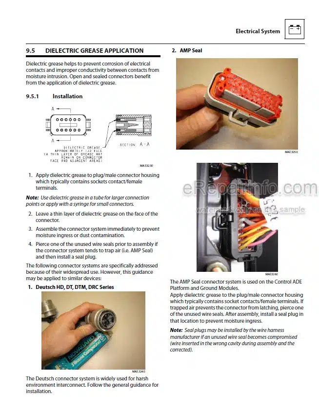
Dielectric Grease Application
Engine Start Circuit
Charging Circuit
Battery
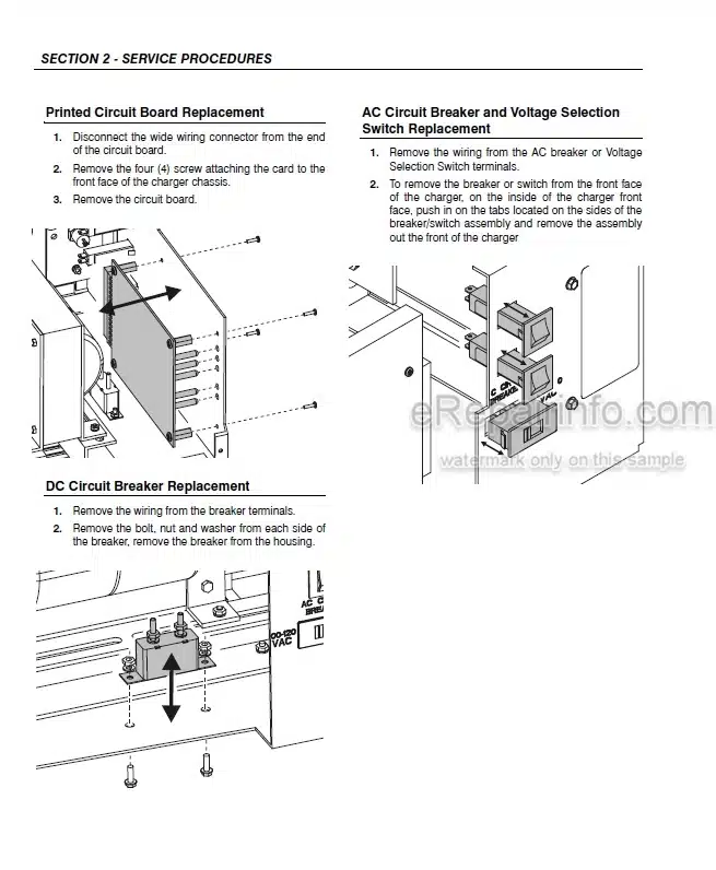
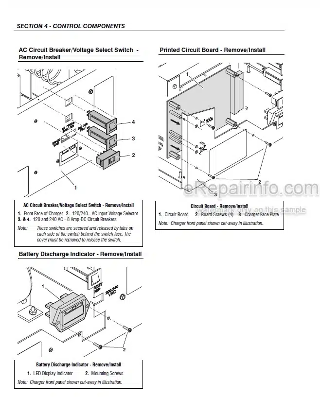
Electrical System Components
Window Wiper/Washer
Cab Heater/AC and Fan
Switches, Solenoids and Senders
Load Stability Indicator (LSI) (2505H & 25.5)
Analyzer
Analyzer Software Accessibility
Telematics Gateway
Diagnostic Trouble Codes (DTC) on Ground Module
Engine Diagnostic Trouble Code
What you get
You will receive PDF file with high-quality manual on your email immediately after the payment.
Reviews
There are no reviews yet