Factory Service Manual For JLG Telehandler. Manual Contains Illustrations, Instructions, Diagrams For Step By Step Remove And Install, Assembly And Disassembly, Service, Inspection, Repair, Troubleshooting, Tune-Ups.
Format: PDF
Language: English
Pages: 266
Issue: july 2002
Bookmarks: Yes
Searchable: Yes
Wiring Diagrams: Yes
Hydraulic Diagrams: Yes
Model
JLG Telehandler
Gradall 534B
Starting S/N 8744110 thru 0144859
Also S/N 8744079 & (534B-9) S/N 0144860 thru S/N 0144899
Contents
-OPERATION AND LUBRICATION MANUAL
Important Safety Notice
Introduction
Nomenclature
Safety Highlights
Hand Signals
Operator’S Cab
Control & Instrument Identification
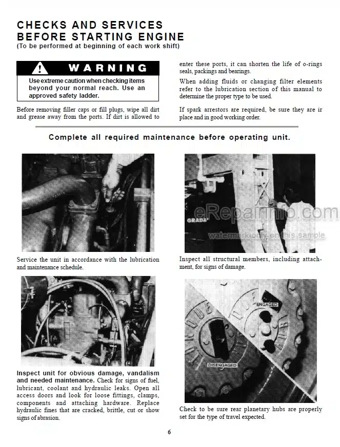
Checks & Services Before Starting Engine
Engine Operation
Warm Up & Operational Checks
Brake System
Steering System
Drive Train
Material Handling
Operating Procedures & Techniques
Parking
Storage
Recommended Lubricants & Capacities
Tire Specifications
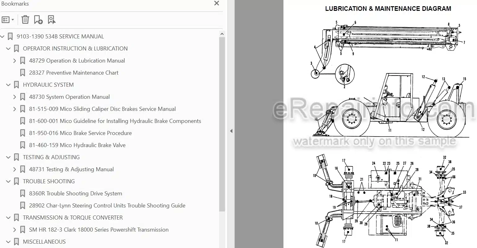
Lubrication & Maintenance Diagram
Lubrication Frequencies
-SYSTEM OPERATION MANUAL
Nomenclature
Control & Instrument Identification
Engine
Electrical & Fuel Tank
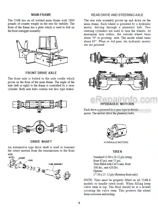
Main Frame, Front Drive Axle, Drive Shaft
Rear Drive & Steering Axle
Hydraulic Motors And Tires
Transmission & Torque Converter
Steering Circuit
Brake Circuit Nomenclature
Hydraulic Service Brakes, Wet Disc Brakes
Service & Parking Brake Applications
Hydraulic System Nomenclature
Hydraulic Cylinders
Main Pump Circuits
Pilot Pump Circuit
Hydraulic Circuits, Sway Circuit
Auxiliary Hydraulic System
Tilt & Compensating Circuits
Crowd Circuit & Movements
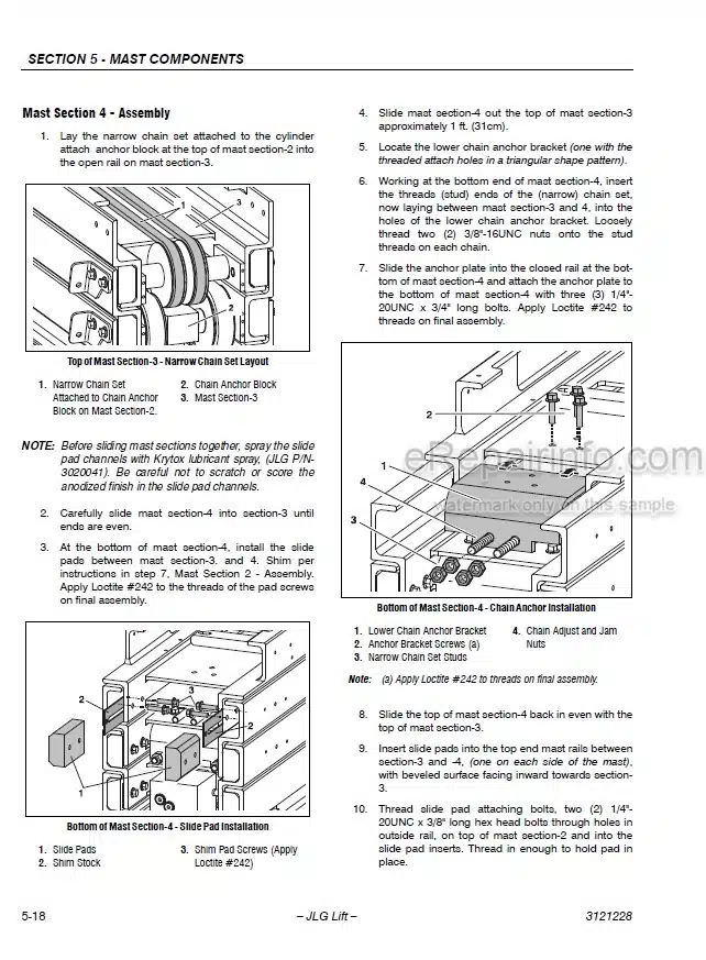
Boom Sections & Slider Pads
Lift Circuit, Manual “Quick Switch” Ass’y
Outrigger Circuits (Optional)
Front & Rear Wheel Drive
Forward/Reverse Lever (Neutral & Shifted)
Inching
Quick Switch Attachments
MICO SLIDING CALIPER DISC BRAKES SERVICE MANUAL
MICO GUIDELINE FOR INSTALLING HYDRAULIC BRAKE COMPONENTS
MICO BRAKE SERVICE PROCEDURE
MICO HYDRAULIC BRAKE VALVE
-TESTING & ADJUSTING MANUAL
Introduction – Pumps
Tools Needed to Test System
How to Test Pump Flow – Test Ports
Hydraulic Pressure Test Ports
Testing Relief Valve Pressures – Adjusting Relief Valves
How to Test and Adjust Main Control Valve Relief
How to Test and Adjust Pilot Pump Relief Valve
Testing and Adjusting Steering Circuit Relief Valve
How to Test Tilt Circuit Relief Valves
How to Test & Adjust Drive Circuit Relief Valves
How to Test Crowd Circuit Relief Valve
Testing the Brake Circuits
How to Test and Adjust the Inching System
How to Check and Adjust the Boom Cables
Boom Slider Pad Adjustment
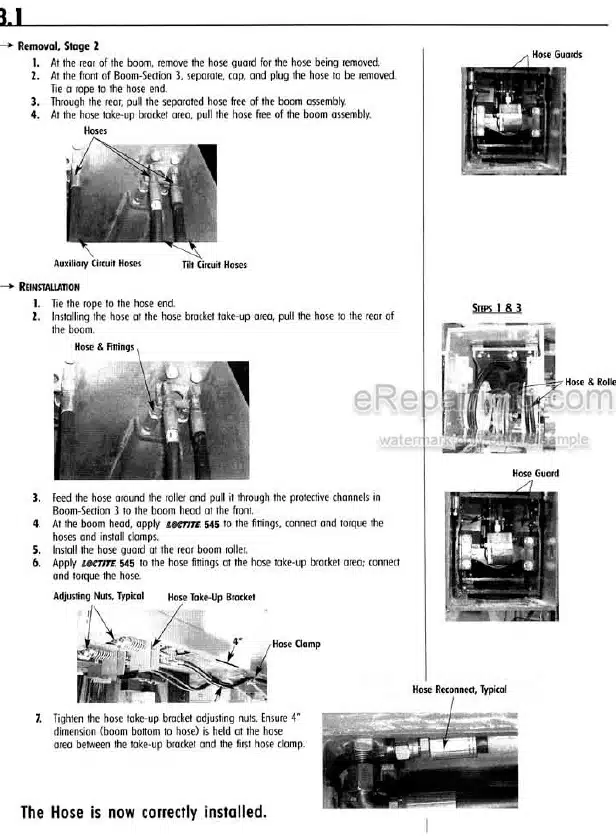
How to Check and Tighten Boom Hoses
Hydraulic Circuit Table of Pressures
Torque Chart
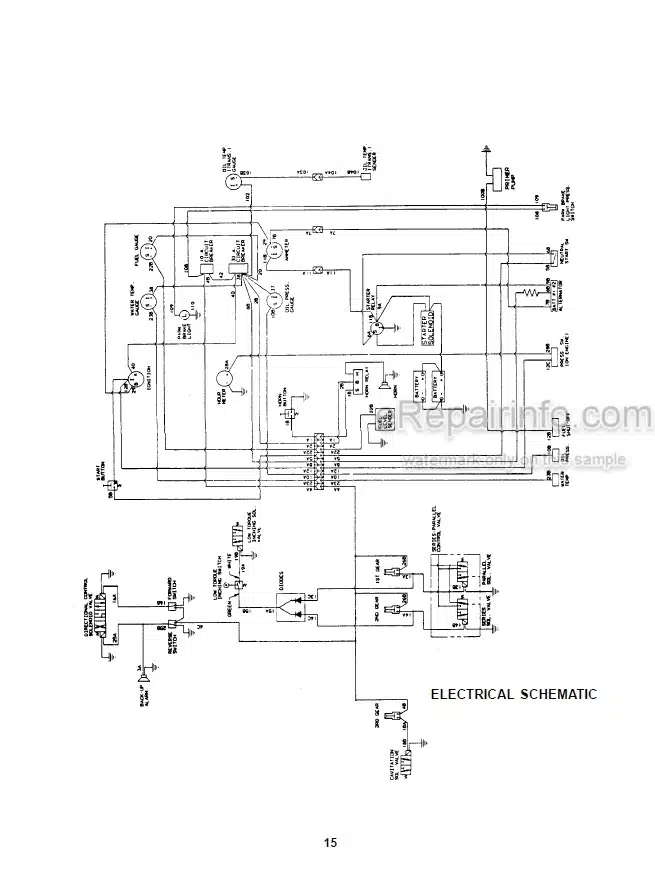
Electric Schematic Drawinq
-TROUBLESHOOTING
Trouble Shooting Drive System
Char-Lvnn Steering Control Units Trouble Shooting Guide
-18000 POWERSHIFT TRANSMISSION
How The Units Operate
Sectional Views And Parts Identification
Disassembly Of Transmission
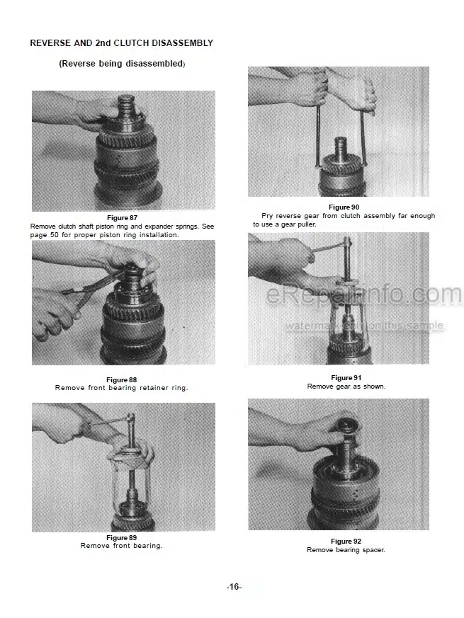
Clutch Disassembly
Cleaning And Inspection
Reassembly Of Transmission
Servicing Machine After Transmission Overhaul
Towing Or Push Starting
Specifications And Service Data
Lubrication
Trouble Shooting Guide
Typical Two And Three Speed Power Flow
Pressure Check Points
Clutch And Gear Arrangement
Drive Plate Installation
Transmission To Engine Installation Procedure
Speed Sensor Bushing Installation
-MISCELLANEOUS
Rim & Wheel Safety Manual
Soma Planetary w/Wet Disc Brake
Soma Maintenance Manual
Toe-in Procedure
Fairfield “A” Drive Torque Hub
Donaldson Cyclopac Service Procedure
What you get
You will receive PDF file with high-quality manual on your email immediately after the payment.
Reviews
There are no reviews yet