Factory Troubleshooting Manual For JLG Boom Lift. Manual Contains Important Information And Instructions Illustrations, Diagrams, Service, Inspection, Repair, Troubleshooting, Tune-Ups, Fault Codes, Use Information Of JLG Devices.
Format: PDF
Language: English
Pages: 225
Number: 3121203 (september 2005)
Bookmarks: Yes
Searchable: Yes
Wiring Diagrams: Yes
Hydraulic Diagrams: Yes
Model
JLG Boom Lift
T350
T500J
Contents
-INTRODUCTION
How To Use This Manual
Visual Inspection
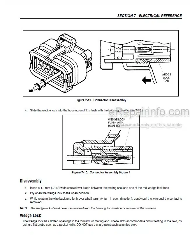
Connector References
Reading Fault Codes
User Fault Codes
User Fault Code Cross References
Service Fault Code Cross References
Power Module Flash Codes
Ground Reference
Control Module Power
Tilt
Critical Vehicle Interlock Scenarios
Outriggers
-TROUBLESHOOTING SAFETY PRECAUTIONS
General
Hydraulic System Safety
Troubleshooting Safety
-TROUBLESHOOTING BY FUNCTION
All Functions Inoperative
Pump Motor Will Not Operate – DC Powered Models
All Functions Inoperative, Engine Starts And Runs – Engine Models
All Functions Inoperative, Pump Motor Runs – Dc Powered Models
Battery Charger Not Functioning Properly
Engine Will Not Crank – Engine Models
Engine Cranks But Will Not Start – Engine Models
Engine High Idle Inoperative – Engine Models
Engine Low Idle Inoperative – Engine Models
Ground Controls Inoperative
Platform Controls Inoperative
Ground Leveling Not Functioning Properly
Lift Down Function Inoperative
Lift Up Function Inoperative
Telescope Out Function Inoperative
Telescope In Function Inoperative
Swing Left Function Inoperative
Swing Right Function Inoperative
Platform Leveling Up Function Inoperative
Platform Leveling Down Function Inoperative
Jib Up Function Inoperative
Jib Down Function Inoperative
Outrigger Set Function Inoperative
Outrigger Stow Function Inoperative
-TROUBLESHOOTING BY FAULT MESSAGES
ADE Codes
-COMPONENT CHECKS
DC Powered Machine – Hydraulic Pump
DC Powered Machine – Power
DC Powered Machine – Power Module
Drive Module – Power
Drive Sensor Reset
Engine Powered Machine – Hydraulic Pump
Engine Powered Machine – Power
Ground Module – Power
Ignition Relay – Power
Joystick Diagnostics
Outrigger Switches – All Set
Outrigger Switches – All Stowed
Platform Module – Power
Power Module – Power
Telescope Limit Switch
Tilt Sensor
Transport Limit Switch
-POSSIBLE CAUSES
Possible Causes
-SYSTEM TEST MESSAGES
Test Messages
-ELECTRICAL REFERENCE
Connector Layout
Valve Connections
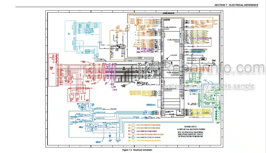
Electrical Schematic
Wiring Diagram
Drive and Set
Connector Index
Ground Module Connector Pinouts
Platform Module Connector Pinout
Drive Module Connector Pinout
Connector Loading Diagrams
Working with AMP Connectors
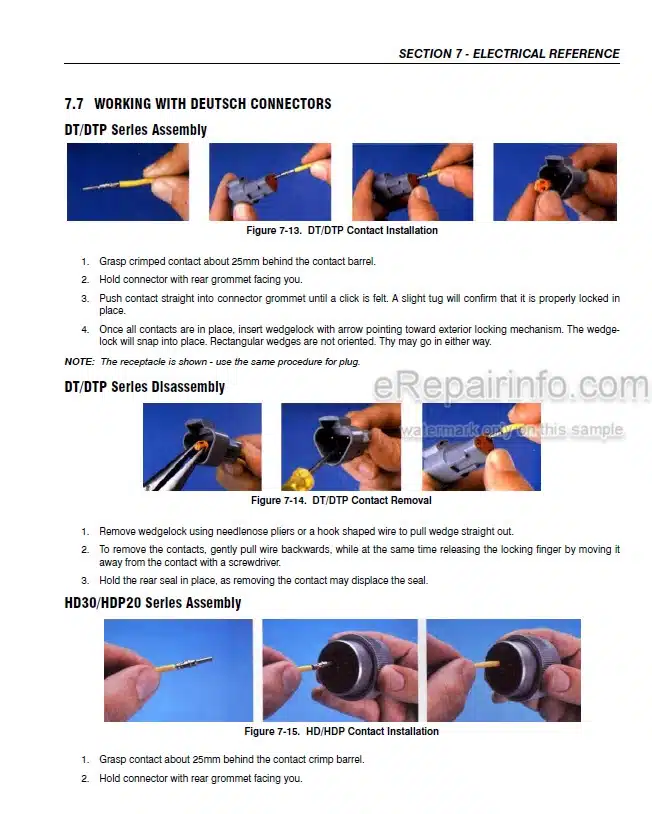
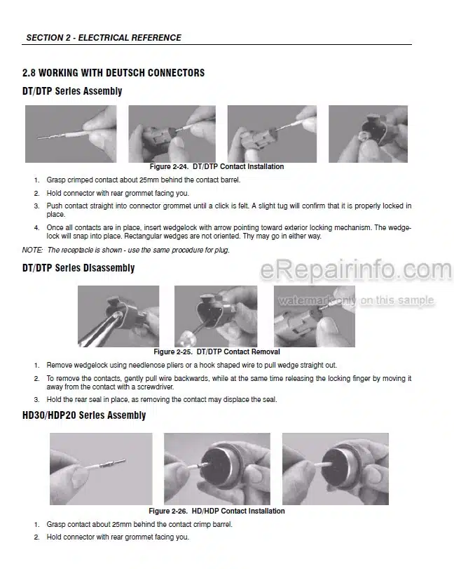
Working with Deutsch Connectors
Trailer Wiring
-HYDRAULIC REFERENCES
Solenoids
Minimum Operating Pressure
Hydraulic Test Ports
Hydraulic Schematic – Electric Powered Machines
Hydraulic Schematic – Engine Powered Machines
Hydraulic Schematic – Engine Powered Drive Option
Hydraulic Schematic – Electric Powered Drive Option
-JLG ANALYZER
Introduction
To Connect the JLG Control System Analyzer
Using the Analyzer
Changing the Access Level of the Hand Held Analyzer
Adjusting Parameters Using the Hand Held Analyzer
Machine Setup
System Test
User Fault Codes
-MULTIMETER BASICS
Introduction
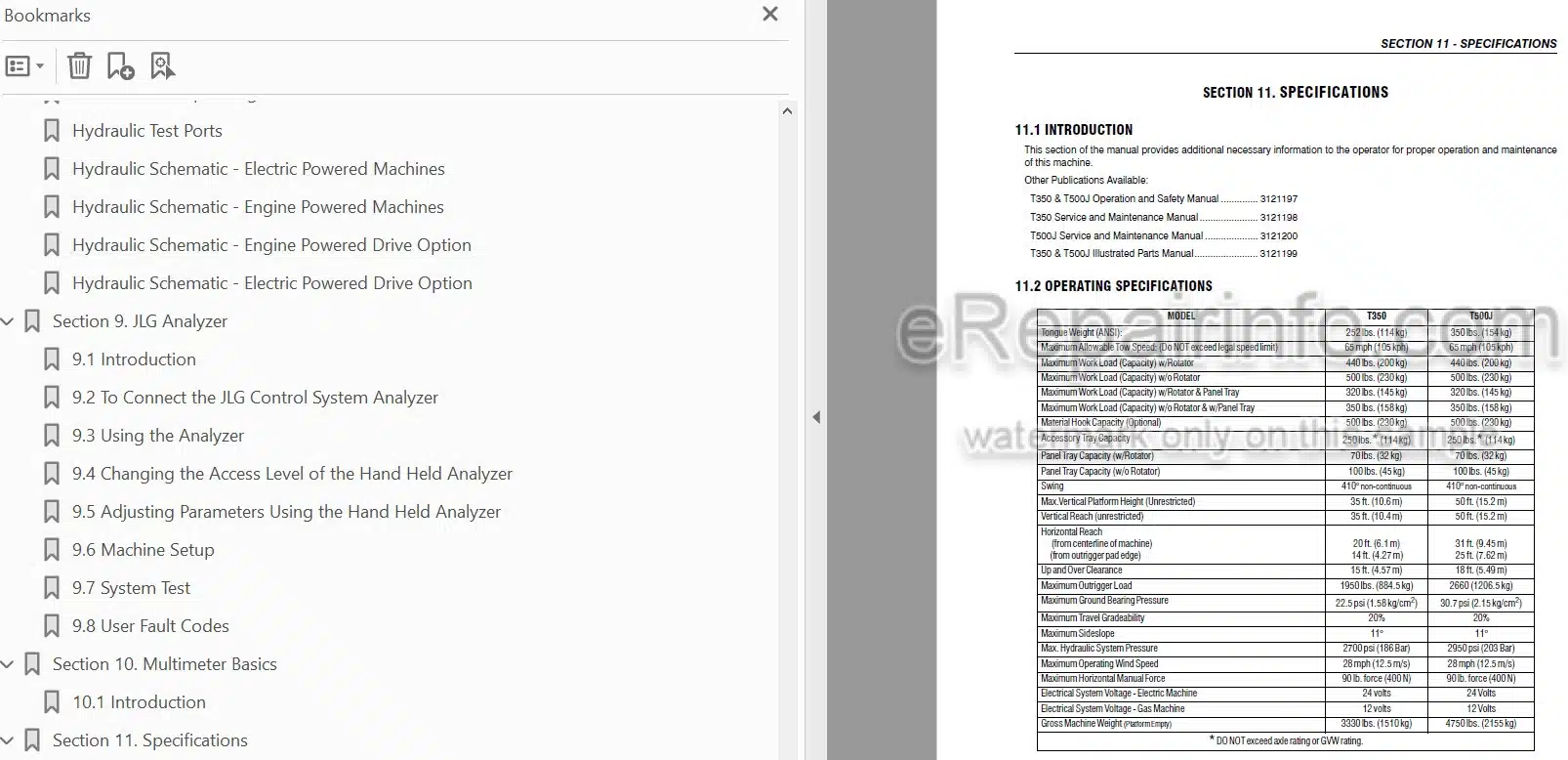
-SPECIFICATIONS
Introduction
Operating Specifications
What you get
You will receive PDF file with high-quality manual on your email immediately after the payment.
Anonymous (verified owner) –
Helpful