Factory Repair Manual CTM125 For John Deere Diesel Engine. Manual Contains Illustrations, Instructions, Diagrams For Step By Step Remove And Install, Assembly And Disassembly, Service, Inspection, Repair, Troubleshooting, Tune-Ups.
Format: PDF
Language: English
Pages: 344
Issued: march 2006
Bookmarks: Yes
Searchable: Yes
Model
John Deere Diesel Engine
Power Tech 2.9L
CD3029DAT01
CD3029DAT50
CD3029DF 164
CD3029DF120
CD3029DF121
CD3029DF122
CD3029DF123
CD3029DF124
CD3029DF128
CD3029DF150
CD3029DF151
CD3029DF152
CD3029DF160
CD3029DF161
CD3029DF162
CD3029DF163
CD3029DF165
CD3029DF166
CD3029DF180
CD3029DF186
CD3029DFG21
CD3029DFG21
CD3029DFG22
CD3029DFG22
CD3029DFG50
CD3029DFG50
CD3029DFG51
CD3029DFG51
CD3029TAT02
CD3029TAT50
CD3029TAT70
CD3029TAT71
CD3029TF270
CD3029TFG21
CD3029TFG21
CD3029TFG50
CD3029TFG50
CD3029TFG51
CD3029TFG51
CD3029TFG71
CD3029TFG71
PE3029DF 150
PE3029DF120
PE3029DF160
PE3029DF180
PE3029DLV51
PE3029DLV52
PE3029DLV53
PE3029DLV53
PE3029DLV54
PE3029DLV55
PE3029DLV56
PE3029DLV57
PE3029DPY05
PE3029DPY06
PE3029TF270
PE3029TLV50
PE3029TLV52
PE3029TLV52
PE3029TLV52
PY3020TPY03
PY3029DPY01
PY3029DPY02
PY3029DPY03
PY3029DPY03
PY3029DPY04
PY3029DPY05
PY3029DPY07
PY3029DPY07
PY3029DPY07
PY3029DPY08
PY3029DPY12
PY3029DPY12
PY3029DPY13
PY3029TPY01
PY3029TPY02
PY3029TPY04
PY3029TPY11
PY3029TPY21
PY3029TPY22
PY3029TPY23
PY3029TPY24
Contents
-SAFETY
Handle Fluids Safely—Avoid Fires
Prevent Battery Explosions
Prepare for Emergencies
Prevent Acid Burns
Avoid High-Pressure Fluids
Wear Protective Clothing
Service Machines Safely
Work In Ventilated Area
Work in Clean Area
Remove Paint Before Welding or Heating
Avoid Heating Near Pressurized Fluid Lines
Illuminate Work Area Safely
Use Proper Lifting Equipment
Practice Safe Maintenance
Use Proper Tools
Dispose of Waste Properly
Live With Safety
-GENERAL INFORMATION
Engine Identification
OEM Engine Option Code Label
Emission Certified Engine Label
Engine References
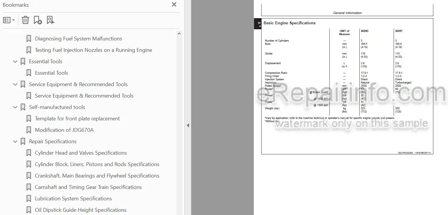
Basic Engine Specifications
Longitudinal Cut-Away
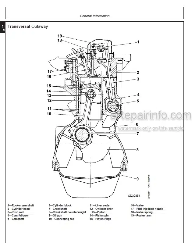
Transversal Cutaway
General Engine Description
Diesel Fuel
Bio-Diesel Fuel
Handling and Storing Diesel Fuel
Diesel Engine Oil
Extended Diesel Engine Oil Service Intervals (Tier 2 Certified Engines Only)
Lubricant Storage
Mixing of Lubricants
Diesel Engine Coolant
Drain Intervals for Diesel Engine Coolant
Operating in Warm Temperature Climates
Metric Bolt and Screw Torque Values
Unified Inch Bolt and Screw Torque Values
-ENGINE MOUNTING
Clean Engine
Engine Lifting Procedure
Engine Repair Stand
Mounting Engine on Repair Stand
-ENGINE REBUILT GUIDE
Engine Disassembly Sequence
Sealant Application Guidelines
Engine Re-Assembly Sequence
Engine break-in guidelines
Perform engine break-in
Diesel Engine Break-In Oil
-CYLINDER HEAD AND VALVES
Cylinder Head – Exploded View
Check Valve Lift
Remove Cylinder Head
Clean Injection Nozzle Bores
Valve Actuating Parts
Remove Valves and Valve Springs
Checking Cylinder Head Flatness
Clean Valve Guides
Measure Valve Guides
Knurl Valve Guides
Clean and Inspect Valve Seats
Lapping Valve Seats
Check Valve Recess
Remove Valve Seat Inserts
Valve Seat Insert Installation
Check Valves
Grind Valves
Check Valve Spring Compression
Inspect Valve Rotators
Install Valves
Install Cylinder Head
Torque Turn Tightening Method
Disassembling and Checking Rocker Arm Shaft
Reassembling Rocker Arm Shaft
Install Rocker Arm Assembly
Valve Clearance
Valve Adjustment Sequence
Install Rocker Arm Cover
Final Work
-CYLINDER BLOCK, LINERS, PISTONS AND RODS
Exploded View
Connecting Rods – General Information
Remove Pistons and Connecting Rods
Measure Cylinder Liner Bore
Remove Cylinder Liners
Cylinder Liner Deglazing
Cylinder Block Cleaning
Check Piston Cooling Jets
Cam Follower Bore Measure
Measure Camshaft Bore
Remove Camshaft Bushing
Install Camshaft Bushing
Measure Crankshaft Bore
Replace Crankshaft Bearing Caps
Cylinder Block Top Desk Flatness
Measure Cylinder Liner Protrusion
Liner Packing Installation
Liner O-Ring Installation
Install Cylinder Liners
Measure Connecting Rod Bearing
Rod Bearing Clearance
Measure Connecting Rod Bushing
Replace Connecting Rod Bushing (3029D)
Replace Connecting Rod Bushing (3029T)
Measure Piston Pin
Clean and Inspect Pistons
Measure Piston Pin Bore
Piston Top Ring Groove
Second and Third Piston Ring Grooves
Piston Head and Skirt Checking
Install Piston Rings
Piston Rings Staggering
Piston/Liner Set Information
Assemble Piston and Connecting Rod
Install Piston and Connecting Rod
Measure Piston Protrusion
Complete Final Assembly
-CRANKSHAFT, MAIN BEARINGS AND FLYWHEEL
Remove Crankshaft Pulley
Install Crankshaft Pulley
Check Pulley Wobble (Engine With Front PTO)
Remove PTO Pulley
Install PTO Pulley
Flywheel Removal
Flywheel Ring Gear Replacement
Install Ball Bearing
Install Flywheel
Remove Crankshaft Rear Oil Seal
Flywheel Housing Replacement
Install Oil Seal/Wear Sleeve
Crankshaft End Play Measure
Remove Crankshaft
Crankshaft Inspection
Crankshaft Identification
Check Crankshaft Journal Diameter
Determine Crankshaft Main Bearing Clearance Using Plastigage
Regrind Crankshaft
Crankshaft Regrinding Guidelines
Micro-Finishing Specifications
Replace Crankshaft Gear
Install Main Bearing Inserts
Install 2-Piece Thrust Bearing
Install 6-Piece Thrust Bearing
Crankshaft Installation
-CAMSHAFT AND TIMING GEAR TRAIN
Remove Crankshaft Front Oil Seal
Remove Timing Gear Cover
Measure Timing Gear Backlash
Camshaft End Play Measure
Remove Camshaft
Measure Camshaft Journal
Measure Height of Cam Lobe
Replace Camshaft Gear
Tachometer Pick-Up Pin Removal
Install Camshaft
Check Cam Follower
Idler Gear End Play Measure
Remove Front Plate
Idler Gear Bushing and Shaft Measure
Idler Gear Bushing Replacement
Remove Idler Shaft
Install Idler Shaft Spring Pin
Install Idler Shafts
Front Plate Gasket
Install Front Plate
Install Upper Timing Gear Train
Install Lower Timing Gear Train
Install Oil Deflector
Timing Gear Cover Identification
Install Timing Gear Cover
Install Crankshaft Front Oil Seal
Install Wear Ring
Install Auxiliary Equipment
-LUBRICATION SYSTEM
Oil Cooler Identification
Remove Oil Cooler
Replace Oil Cooler Nipple
Install Oil Cooler on Standard Engine
Replace Oil Cooler/Filter Bracket on Engine with Auxiliary Drive
Replace Oil Filter Adapter on Engine with Remote Oil Filter
Remove Oil Pressure Regulating Valve
Replace Oil Pressure Regulating Valve Seat
Install Oil Pressure Regulating Valve
Replace Oil Dipstick Guide
Replace Oil By-Pass Valve
Oil Pump – Exploded View
Replace Oil Pump Strainer
Remove Oil Pump
Oil Pump Gear Axial Clearance
Oil Pump Gear Radial Clearance
Oil Pump Specifications
Oil Pump Installation
Install Oil Pan
-COOLING SYSTEM
Water Pump — Exploded View
Remove Water Pump
Disassemble Water Pump
Assemble Water Pump
Install Water Pump
Inspect Thermostat
Cold Start Advance Switch
Cooling System Deaeration
Check Fan/Alternator Belt Tension
Install Fan
Coolant Heater
Radiator Exploded View
-AIR INTAKE AND EXHAUST SYSTEM
Check Air Inlet Pipe
Exhaust Manifold Inspection
Remove Turbocharger
Turbocharger Cut-Away View (Borg-Warner/Schwitzer)
Check Radial Clearance
Check Axial Clearance
Repair Turbocharger
Prelube Turbocharger
Install Turbocharger
Turbocharger Break-In
Recommendations for Turbocharger Use
Remove and Install Air Heater Glow Plug
Air Filter Exploded View
-FUEL SYSTEM
Replace Fuel Filter Element (Rotary Fuel Injection Pump)
Replace Fuel Filter Assembly (Rotary Fuel Injection Pump)
Replace Fuel Filter Assembly (MICO in-Line Injection Pump)
Replace Fuel Filter Element (MICO in-Line Injection Pump)
Replace Fuel Supply Pump (Rotary Fuel Injection Pump)
Remove STANADYNE DB2 or DB4 Fuel Injection Pump
Repairs to STANADYNE Fuel Injection Pump
Replace Throttle Lever (STANADYNE)
Aneroid Replacement (STANADYNE)
Aneroid Field Adjustment (STANADYNE)
Aneroid Workshop Adjustment (STANADYNE)
Install STANADYNE DB2 or DB4 Fuel Injection Pump
Remove DELPHI/LUCAS Fuel Injection Pump
Repairs to DELPHI/LUCAS Fuel Injection Pump
Install DELPHI/LUCAS Fuel Injection Pump
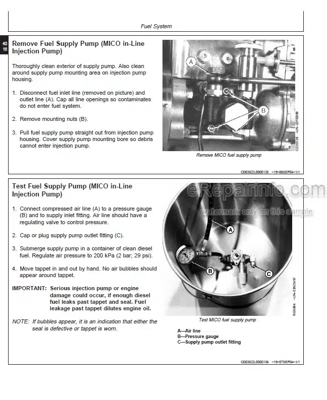
Remove Fuel Supply Pump (MICO in-Line Injection Pump)
Test Fuel Supply Pump (MICO in-Line Injection Pump)
Disassemble Fuel Supply Pump (MICO in-Line Injection Pump)
Disassemble Fuel Supply Pump (MICO in-Line Injection Pump)
Assemble Fuel Supply Pump (MICO in-Line Injection Pump)
Install Fuel Supply Pump (MICO in-Line Injection Pump)
Service Injection Pump Overflow Valve (MICO in-Line Injection Pump)
Modification of JDG670A
Remove MICO in-Line Fuel Injection Pump
Repair MICO in-Line Fuel Injection Pump
Install MICO in-Line Fuel Injection Pump
Dynamic Timing
Install Timing Sensor
Install Magnetic Probe
Timing Sensor and Magnetic Probe Connection
Check Fuel Injection Pump Timing
Fuel Injection Nozzle Identification
Remove Fuel Injection Nozzle
Clean Fuel Injection Nozzle
Fuel Injection Nozzle Test
Fuel Injection Nozzle Disassembly
Adjust Fuel Injection Nozzle
Install Fuel Injection Nozzle
Bleed Fuel System
Check Engine Speed on Rotary Fuel Injection Pump
Check Engine Speed on MICO in-Line Fuel Injection Pump
-ENGINE TUNE-UP
Preliminary Engine Testing
General Tune-Up Recommendations
-ENGINE SYSTEM – OPERATION
Lubrication System
Cooling System
-ENGINE SYSTEM – DIAGNOSIS AND TESTS
Diagnose Engine Malfunctions
Checking Engine Compression
Check Engine Oil Pressure
Measure Engine Blow-By
Using Stanadyne “TIME-TRAC” as Tachometer
Inspect Thermostat and Test Opening Temperature
Pressure Test Cooling System and Radiator Cap
-AIR INTAKE SYSTEM – OPERATION AND TESTS
Turbocharger Operation
Wastegate Operation
Test Turbocharger Wastegate
Check Turbocharger Boost Pressure
Diagnosing Turbocharger Malfunctions
-FUEL SYSTEM – OPERATION AND TESTS
General Operation (Rotary Fuel Injection Pump)
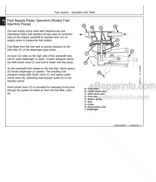
Fuel Supply Pump Operation (Rotary Fuel Injection Pump)
Measure Fuel Supply Pump Pressure (Rotary Fuel Injection Pump)
Fuel Filter Operation (Rotary Fuel Injection Pump)
STANADYNE Fuel Injection Pump (DB2/DB4) – Operation
DELPHI/LUCAS Fuel Injection Pump (DP200 shown) – Operation
Test Shut-Off Solenoid on DELPHI/LUCAS Injection Pump
Cold Start Advance System Operation
Check Cold Start Advance System Operation
Check Cold Start Switch Operation
Light Load Advance Operation
Check Light Load Advance Operation
General Operation (MICO in-Line Fuel Injection Pump)
Fuel Supply Pump Operation (MICO in-Line Fuel Injection Pump)
Diagnose Fuel Supply Pump Malfunctions (MICO in-Line Fuel Injection Pump)
Fuel Filter Operation (MICO in-Line Fuel Injection Pump)
MICO in-Line Fuel Injection Pump Operation
Governor Operation (MICO in-Line Fuel Injection Pump)
Diagnose MICO in-Line Fuel Injection Pump Malfunctions
Fuel Injection Nozzles – General Information
Diagnosing Fuel System Malfunctions
Testing Fuel Injection Nozzles on a Running Engine
-ESSENTIAL TOOLS
Essential Tools
-SERVICE EQUIPMENT & RECOMMENDED TOOLS
Service Equipment & Recommended Tools
-SELF-MANUFACTURED TOOLS
Template For Front Plate Replacement
Modification of JDG670A
-REPAIR SPECIFICATIONS
Cylinder Head and Valves Specifications
Cylinder Block, Liners, Pistons and Rods Specifications
Crankshaft, Main Bearings and Flywheel Specifications
Camshaft and Timing Gear Train Specifications
Lubrication System Specifications
Oil Dipstick Guide Height Specifications
Cooling System Specifications
Distance from Pulley or Hub to Water Pump Housing Sealing Surface Specifications
Air Intake and Exhaust System Specifications
Fuel System Specifications
-DIAGNOSTIC AND TEST SPECIFICATIONS
Diagnostic and Test Specifications
What you get
You will receive PDF file with high-quality manual on your email immediately after the payment.
Reviews
There are no reviews yet