Factory Diagnostic Technical Manual For John Deere Combine. Manual Contains Illustrations, Instructions, Diagrams For Systems Diagnosis, Theory Of Operation, Performance Testing, Tests And Adjustments, Operational Check, Unit Locations, Diagnostic Codes, Schematics And A Lot Of Other Useful Information For Service And Repair Remove And Install, Assembly And Disassembly, Inspection, Troubleshooting, Tune-Ups.
Format: PDF
Language: English
Quantity of Manuals: 8 (ZIP File)
Pages: 3364; 2740; 3364; 3162; 2664; 2940; 3952; 2400
Number: TM154419 (june 2020; may 2020; june 2020; june 2020; may 2020; june 2020; july 2020; may 2020)
Searchable: Yes
Wiring Diagrams: Yes
Model
John Deere Combine
X Series
Contents
—GENERAL
Safety
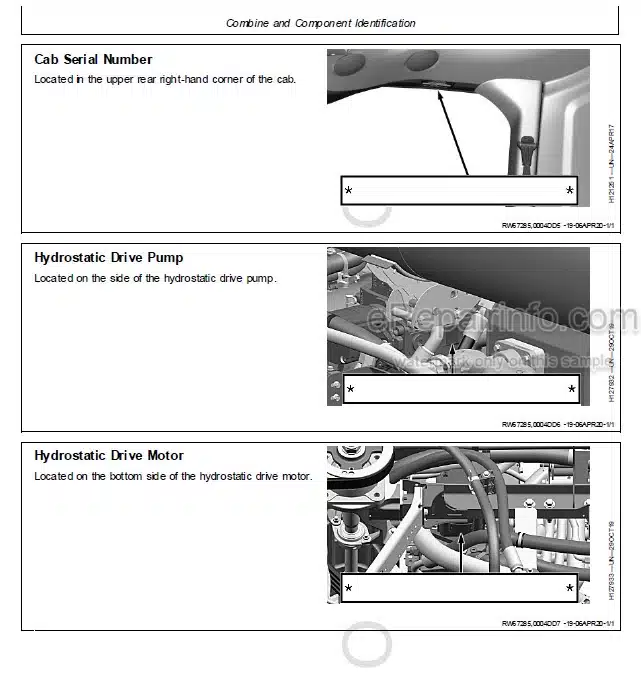
Combine and Component Identification
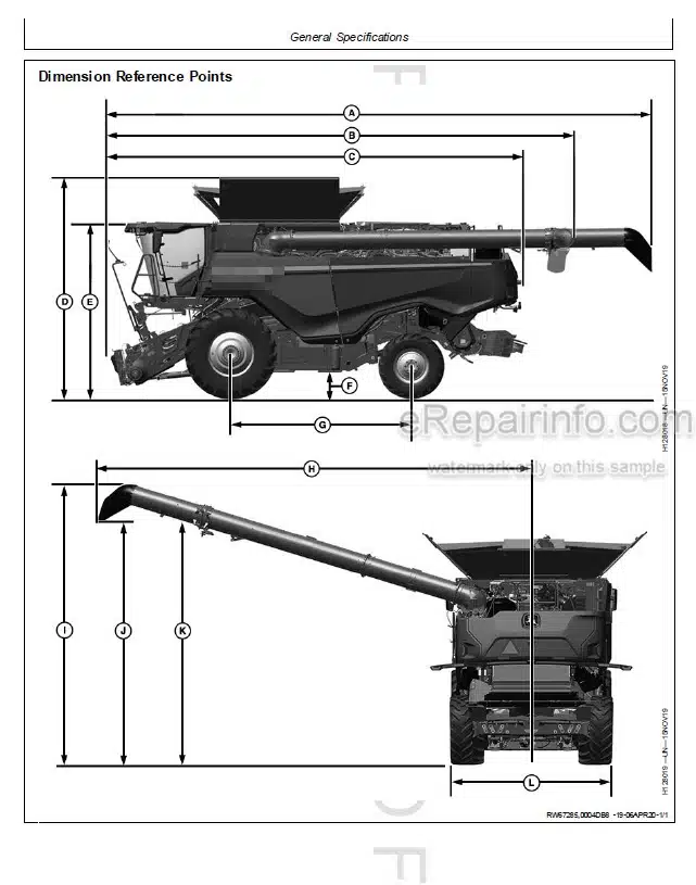
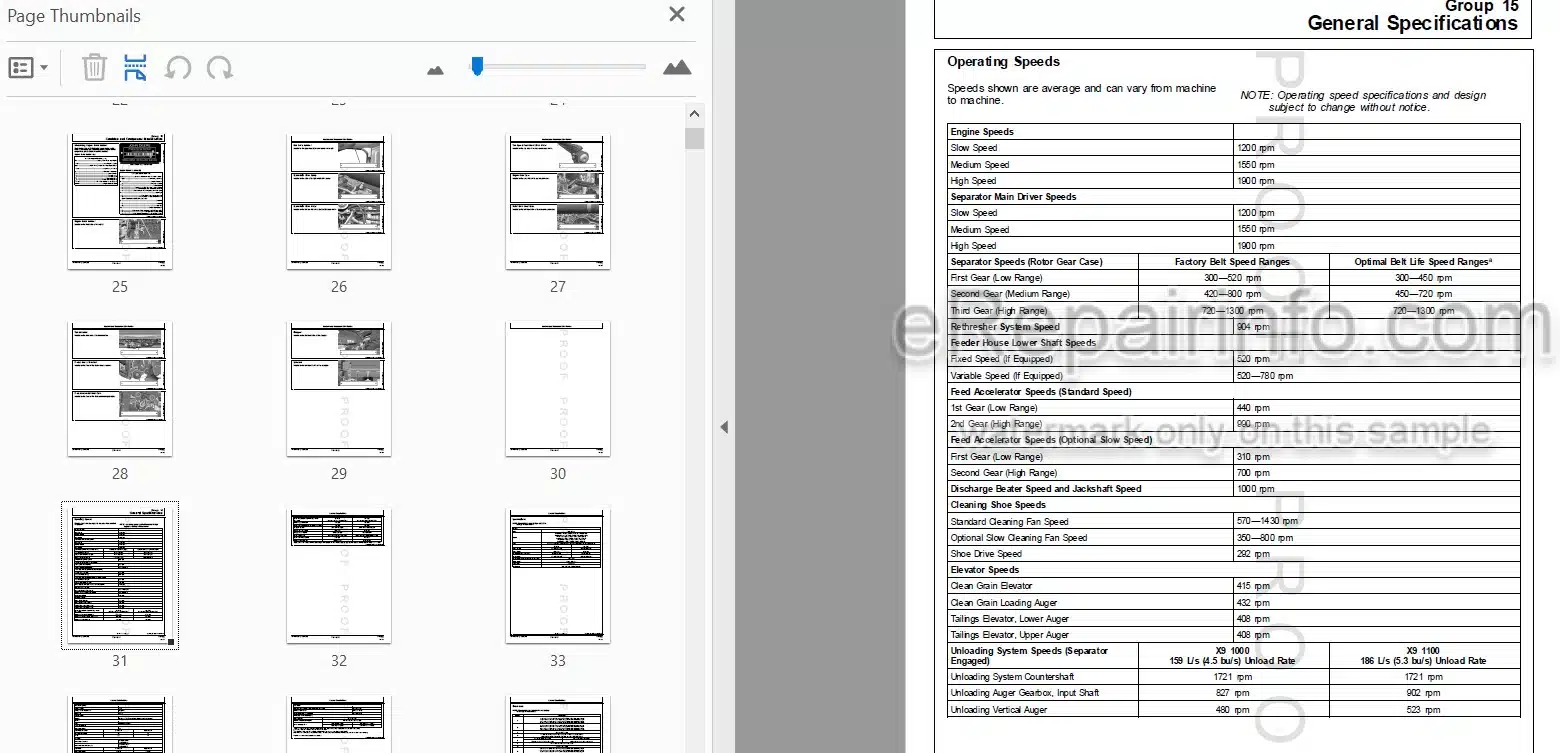
General Specifications
General Specifications (Europe and Eurasian Economic Union)
Diagnostic and Testing Procedures
-DIAGNOSTIC TROUBLE CODES
AYM – Diagnostic Trouble Codes
HCU – BP Model Headers on X-Series
LC1 – BP Model Headers on S-Series
HCU – C-F, C-R Model Headers on X-Series
LC1 – C-F, C-R Model Headers on S-Series
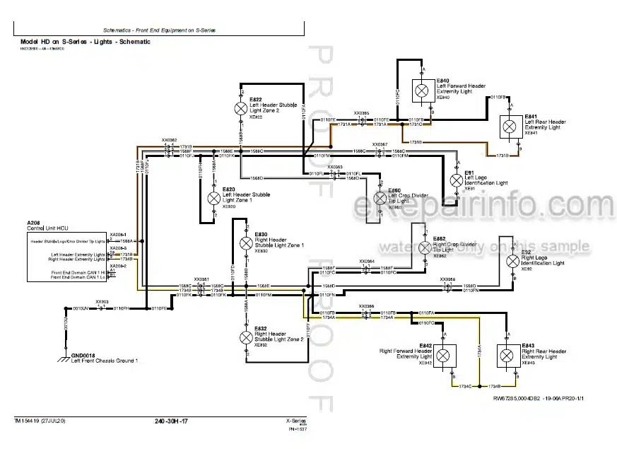
HCU – HD Model Headers on S-Series
HCU – HD Model Headers On X-Series
LC1 – RD-F Model Headers on S-Series
HCU – RD-F Model Headers on X-Series
HCU – 700X WF Model Headers on X-Series
LC1 – 740X WF Model Header on S-Series
MHC – Diagnostic Trouble Codes
MSC – Diagnostic Trouble Codes
-OBSERVABLE SYMPTOMS
Fuel, Air Intake, and Cooling System
Electrical Systems
Electrical Control Units
Drives
Steering and Brakes
Hydraulic Systems
Main Gear Case
Cab Operator Station
-ENGINE SYSTEM
Engine System
—FUEL, AIR INTAKE, EXHAUST, AND COOLING SYSTEMS
Theory of Operation
Schematics
Diagnostics
—AIR INTAKE AND COOLING SYSTEM – COMPONENTS
Air Intake and Cooling System – Components
Summary of References
Fuel Components
Air Intake Components
-ELECTRICAL SYSTEM
General information
Calibration Procedures
Theory of Operation
Schematics
Diagnostics
—ELECTRICAL CONTROL UNITS
General Information
Accessing Diagnostic Trouble Codes,
Addresses, and Templates
Theory of Operation
Schematics
Diagnostics
AIC – Diagnostic Addresses
ATC – Data Identifiers (DID)
ATX – Diagnostic Identifiers (DID)
AYM – Diagnostic Addresses
CAB – Diagnostic Addresses
CFDE
ESU – Diagnostic Addresses
FCDE
FEDC – Data Identifiers (DID)
GLM1
GLM2
GQM – Diagnostic Addresses
HA DC – Data Identifiers (DID)
HADE
HCU – Data Identifiers (DID)
IPM—IPM
MHC—MHC – Diagnostic Addresses
MSC—MSC – Diagnostic Addresses
MTG—MTG
OSDC—OSDC
PDU—PDU – Diagnostic Addresses
POD—POD – Data Identifier piD)
PTP—PTP – Data Identifiers piD)
SCCM—SCCM
SVDE—SVDE
TLM—TLM – Diagnostic Addresses
DS—Display Server
-ELECTRICAL CONNECTOR/COMPONENTS
Electric Connector/Component Summary of References
General Information
XA – Electrical Assembly Connectors
XB – Sensor Connectors
XE – Lighting Connectors
XF – Fuse Connectors
XG – Power Supply Connectors
XH – Monitor, Alarm, Signaling Device Connectors
XK – Relay Connectors
XM – Motor Connectors
XR – Resistor Connectors
XS – Switch Connectors
XX – Inline Connectors
XY – Electrically Actuated Device Connectors
GND – Ground Points
Ground Straps
XW – Antenna
Header Model BP- Connectors
Header Model C-F, C-R – Connectors
Header Model HD – Connectors
Header Model RD-F – Connectors
Header Model 740X WF – Connectors
Duplicates Removed
—GROUND DRIVES
Preliminary and Operational Checks
Hydrostatic Specifications
Theory of Operation
Schematics
Diagnostics
—GROUND DRIVES
Preliminary and Operational Checks
Hydrostatic Specifications
Theory of Operation
Schematics
Diagnostics
—DRIVES – COMPONENTS
Drives – Components – Summary of References
—STEERING AND BRAKES
Preliminary and Operational Checks
Hydraulic Specifications
Steering and Brakes – Theory of Operation
Steering and Brakes – Schematics
Steering and Brakes – Diagnostics
—STEERING AND BRAKES – COMPONENTS
Steering and Brakes – Components – Summary of References
—HYDRAULIC SYSTEM
Preliminary and Operational Checks
Hydraulic Specifications
Theory of Operation
Schematics
Diagnostics
-MODEL C-R – RIGID CORN HEAD HYDRAULICS
Preliminary & Operational Checks
Hydraulic Specifications
Theory of Operation
Schematics
Diagnostics
-MODEL CF – FOLDING CORN HEAD HYDRAULICS
Preliminary & Operational Checks
Hydraulic Specifications
Theory of Operation
Schematics
Diagnostics
-MODEL RD-F – RIGID DRAPER – FLEX KNIFE – HEAD HYDRAULICS
Preliminary & Operational Checks
Hydraulic Specifications
Group 20—Theory of Operation
Group 30—Schematics
Group 50—Diagnostics
-MODEL BP15 – BELT PICKUP HEAD HYDRAULICS
Preliminary & Operational Checks
Hydraulic Specifications
Theory of Operation
Schematics
Diagnostics
-MODEL 700X-WIDE FEED – EXTENDABLE TABLE HEAD HYDRAULICS
Preliminary & Operational Checks
Hydraulic Specifications
Theory of Operation
Schematics
Diagnostics
-MODEL HD – HINGED DRAPER HEAD HYDRAULICS
Preliminary & Operational Checks
Hydraulic Specifications
Theory of Operation
Schematics
Diagnostics
-PLACE HOLDER
Preliminary & Operational Checks
Hydraulic Specifications
Theory of Operation
Schematics
Diagnostics
-HYDRAULIC – COMPONENTS
Hydraulic – Components – Summary of References
Accumulator
Sensor or Gauge
Cylinder, Actuator, or Piston
Check Valve
Filter
Drive Belt
Valve Block, Assembly, or Gear Case
Cooler
Motor
Orifice
Pump
Reservoir or Tank
Switch
Valve
Mechanical Assembly
Diagnostic Receptacle or Coupler
Solenoid Valve
-MAIN GEAR CASE
Preliminary and Operational Checks
Hydraulic Specifications
Theory of Operation
Schematics
Diagnostics
-MAIN GEAR CASE – COMPONENTS
Main Gear Case – Components – Summary of References
-CAB/OPERATOR’S STATION
Specifications
Theory of Operation
Schematics
Diagnostics
-CAB COMPONENT INFORMATION
Components – Summary of Reference
Cab Components
What you get
You will receive PDF file with high-quality manual on your email immediately after the payment.


Reviews
There are no reviews yet