Factory Shop Manual For Komatsu Wheel Loader. Manual Contains Illustrations, Instructions, Diagrams For Step By Step Remove And Install, Assembly And Disassembly, Service, Inspection, Repair, Troubleshooting, Tune-Ups.
Format: PDF
Language: English
Pages: 421
Number: SEBM012402 (july 1997)
Bookmarks: Yes
Wiring Diagrams: Yes
Hydraulic Diagrams: Yes
Model
Komatsu Wheel Loader
Avance WA120-3CS
SN 10004 And Up
Contents
-GENERAL
General Assembly Drawing
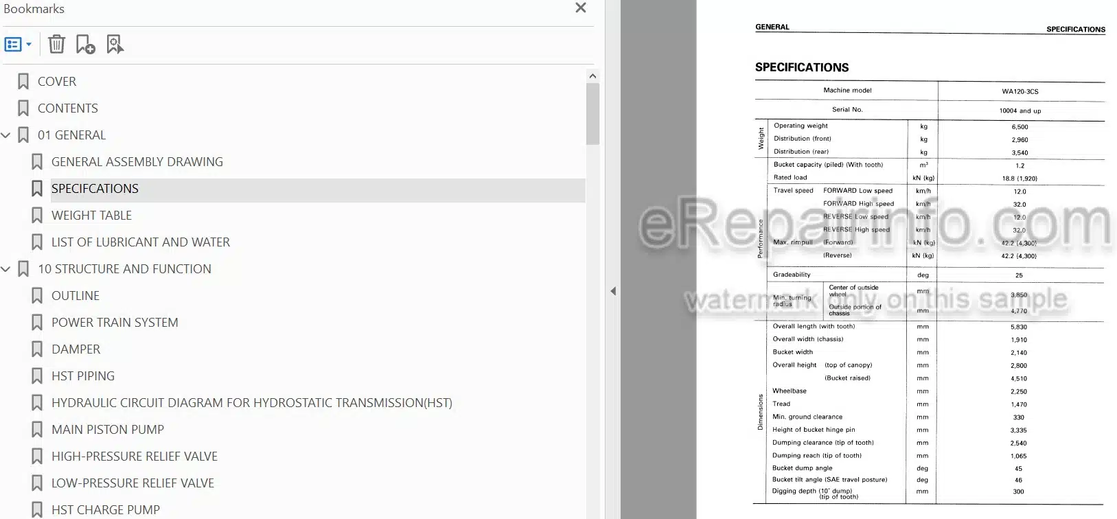
Specifications
Weight Table
List Of Lubricant And Water
-STRUCTURE AND FUNCTION
Outline
Powertrain System
Damper
HST Piping
Hydraulic Circuit Diagram For Hydrostatic Transmission(HST)
Main Piston Pump
High-Pressure Relief Valve
Low-Pressure Relief Valve
HST Charge Pump
Charge Pump Oil Filter
Speed Related Valve(Da Valve)
High-Pressure Cut-Off Valve
Piston Motor
Directional Shuttle Valve
Servo Valve
Intermediate Fixed Control Of Angle
Inching Valve
Transfer
HST Control
Drive Shaft
Axle
Differential
Final Drive
Axle Mount
Center Hinge Pin
Steering Piping
Steering Column
Priority Valve
Steering Valve(Orbit-Roll)
Brake Piping
Brake Control
Brake
Brake Master Cylinder
Parking Brake Control
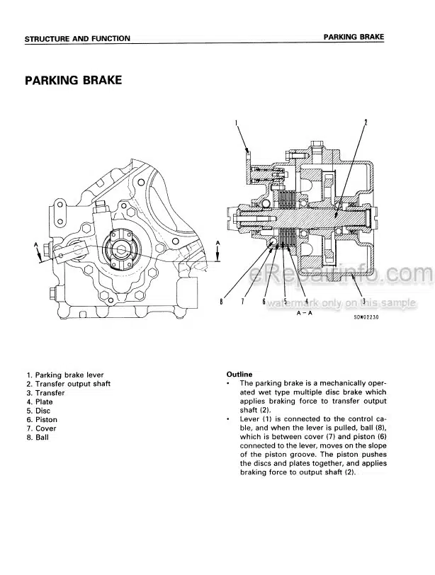
Parking Brake
Hydraulic Piping
Work Equipment Hydraulic Circuit Diagram
Work Equipment Lever Linkage
Hydraulic Tank
Hydraulic Filter
Main Control Valve
Work Equipment Linkage
Bucket
Bucket Positioner
Proximity Switch
Canopy
Electric Circuit Diagram
Central Panel(Cluster Gauge)
Sensor
Engine Starting Circuit
Engine Stop Circuit
Parking Brake Circuit
-TESTING AND ADJUSTING
Standard Value Table For Engine
Standard Value Table For Chassis
Standard Value Table For Electrical Parts
Table Of Tools For Testing, Adjusting And Troubleshooting
Measuring Engine Speed
Measuring Exhaust Color
Adjusting Valve Clearance
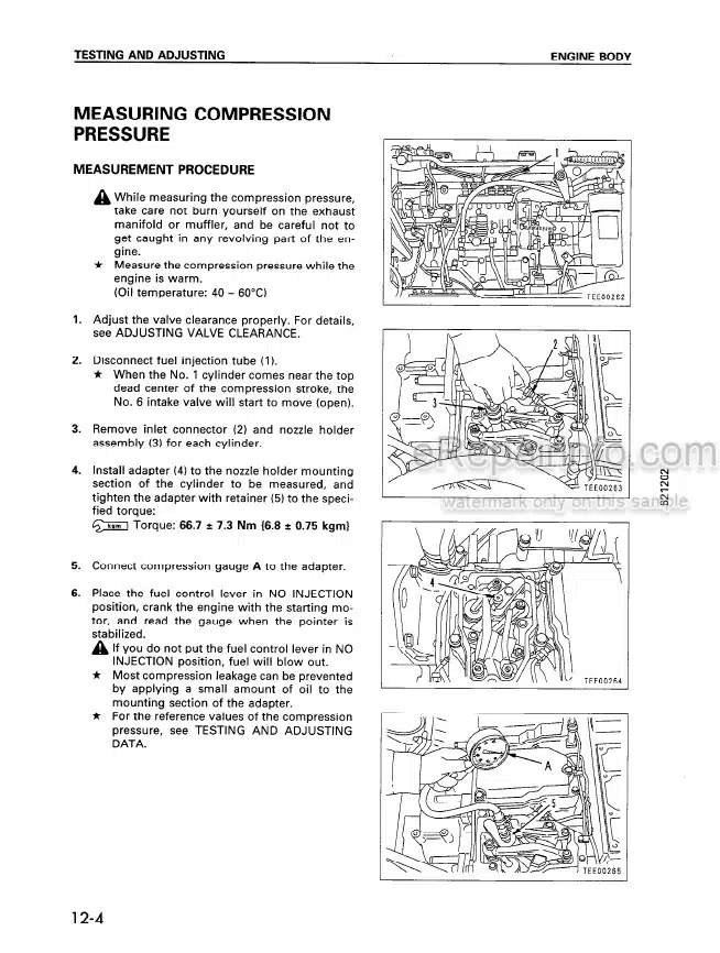
Measuring Compression Pressure
Measuring Blow-By Pressure
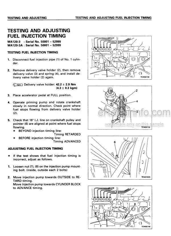
Testing And Adjusting Fuel Injection Timing
Measuring Engine Oil Pressure
Testing And Adjusting Fan Belt Tension
Method For Adjusting Engine Stop Motor Cable
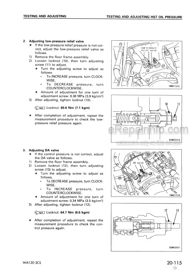
Testing And Adjusting HST Oil Pressure
Testing And Adjusting Steering Oil Pressure
Bleeding Air From Steering Circuit
Measuring Brake Performance
Testing Drop In Wheel Brake Oil Pressure
Measuring Wheel Brake Disc Wear
Bleeding Air From Wheel Brake Circuit
Adjusting Wheel Brake Linkage
Measuring Parking Brake Performance
Testing And Adjusting Parking Brake Linkage
Measuring Work Equipment Hydraulic Pressure
Bleeding Air From Work Equipment Circuit
Adjusting Work Equipment Lever Linkage
Testing And Adjusting Bucket Positioner
Troubleshooting
-DISASSEMBLY AND ASSEMBLY
Method Of Using Manual
Precautions When Carrying Out Operation
Special Tool List
Sketches Of Special Tools
Starting Motor
Alternator
Fuel Injection Pump
Nozzle Holder
Water Pump
Thermostat
Engine Oil Cooler
Cylinder Head
Radiator
Engine, Hydraulic Pump
Fuel Tank
Damper
HST Pump
HST Motor
Transfer
Front Axle
Rear Axle
Axle
Center Hinge Pin
Steering, Hydraulic Pump
Steering Valve
Steering Cylinder
Brake Master Cylinder
Inching Valve
Hydraulic Tank
Main Control Valve
Boom Cylinder
Bucket Cylinder
Boom, Bucket Cylinder
Bucket
Boom
Engine Hood
Canopy
Floor Frame
Counterweight (Rear End)
Counterweight (Lower Portion)
Monitor Panel
-MAINTENANCE STANDARD
Engine Mount
Transfer Mount
Transfer
HST Inching Valve
Drive Shaft
Differential
Final Drive
Axle Mount
Center Hinge Pin
Steering Column
Priority Valve
Steering Cylinder Mount
Parking Brake
Hydraulic And Steering Pump
Hydraulic Cylinder
Work Equipment Linkage
Bucket
Bucket Positioner
-OTHERS
Electric Circuit Diagram
What you get
You will receive PDF file with high-quality manual on your email immediately after the payment.

Reviews
There are no reviews yet