Factory Shop Manual For Komatsu Forklift Truck. Manual Contains Illustrations, Instructions, Diagrams For Step By Step Remove And Install, Assembly And Disassembly, Service, Inspection, Repair, Troubleshooting, Tune-Ups.
Format: PDF
Language: English
Pages: 341
Number: SM181
Wiring Diagrams: Yes
Hydraulic Diagrams: Yes
Model
Komatsu Forklift Truck
DX20 Series
FG50-7
FG60-7
FG70-7
FD50E-7
FD60E-7
FD70E-7
FD50-7
FD60-7
FD70-7
FD80-7
SN 40001 And Up
Contents
-GENERAL AND SPECIFICATIONS
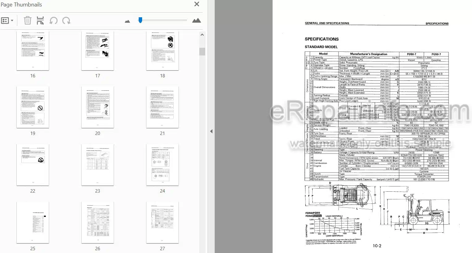
Specifications
Periodic Replacement Of Consumable Parts
Safety Items For Maintenance
Standard Tightening Torque For Bolts
Standard Tightening Torque For Pipe
-TESTING AND ADJUSTING
Service Data
Diesel Engine
Gasoline Engine
Air Cleaner
Method Of Adjusting Ignition Timing
Method Of Adjusting Injection Timing
Engines Fitted With Standyne Fuel Injection Pumps
Measuring Method For Compression
Adjustment Of Valve Clearance
Tightening Torque For Cylinder Head Mounting Bolts
Adjusting Accelerator Pedal
Adjusting Inching/Brake Pedal
Wheel Brake
Adjusting Parking Brake
Torqflow Transmission Case
Differential Case
Hydraulic Tank
Measuring Hydraulic Drift Of Lift Cylinder, Tilt Cylinder
Adjusting Mast
Adjusting Fork Carriage
Cooling System
Bleeding Air
Specified Fuel, Lubricating Oil, And Fluid
Lubricating Table
-REMOVAL AND INSTALLATION
Engine
Power Train
Travel System
Steering System
Braking System
Load System
Hydraulic System
Body Safety System
Overall Test
-DISASSEMBLY AND ASSEMBLY
Unit Assembly Position
List Of Parts Mass
Disassembly And Assembly Flowchart
Overall Disassembly And Assembly Drawing
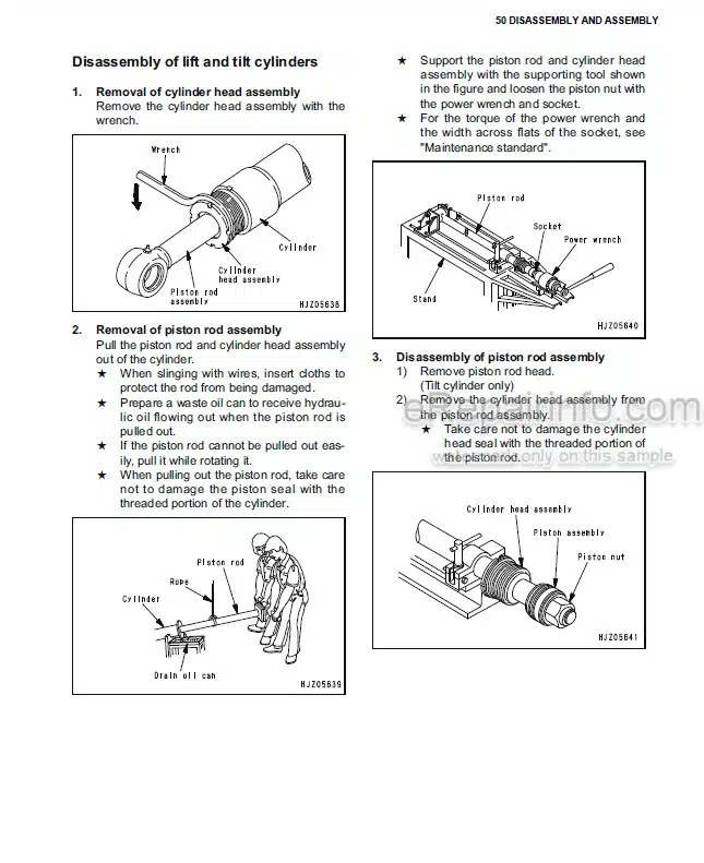
Lift Cylinder
Mast
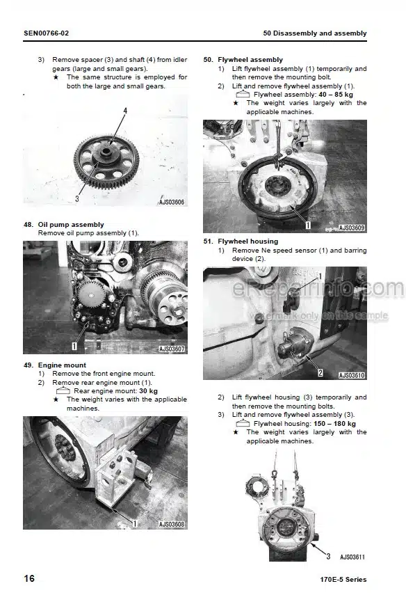
Engine
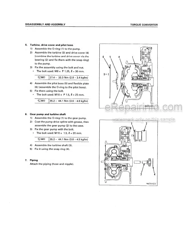
Torque Converter + Transmission
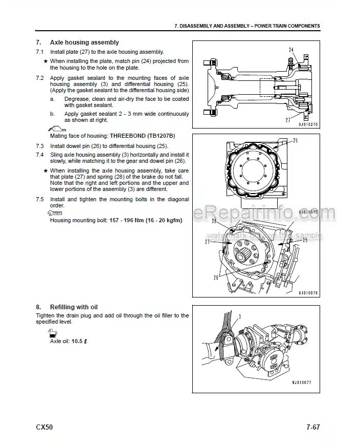
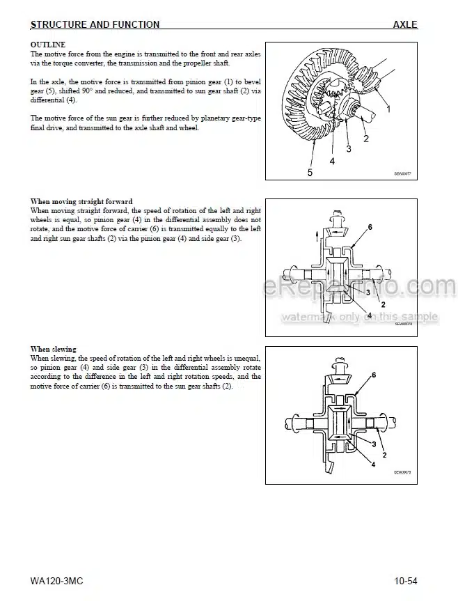
Drive Axle
Steering Axle And Power Steering
Wheel Brake
-MAINTENANCE STANDARD
Disassembly Drawing
Torque Converter
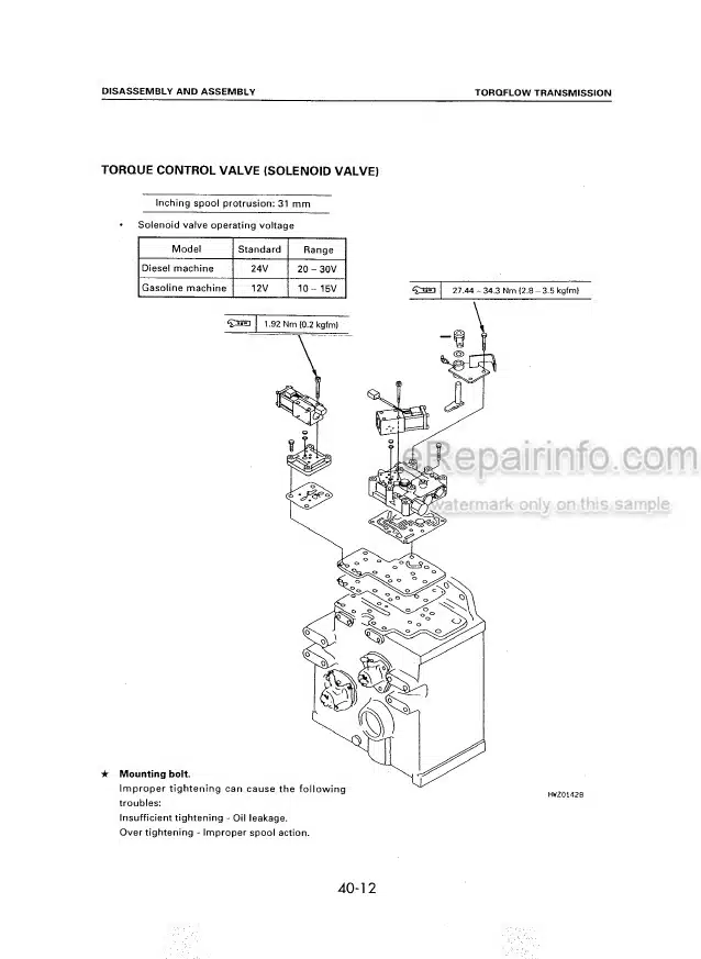
Torqflow Transmission
Propeller Shaft
Differential
Drive Axle (Front Axle)
Wheel Brake
Parking Brake
Steering Axle (Rear Axle)
Brake Pedal
Combination Switch
Master Back And Master Cylinder Assembly
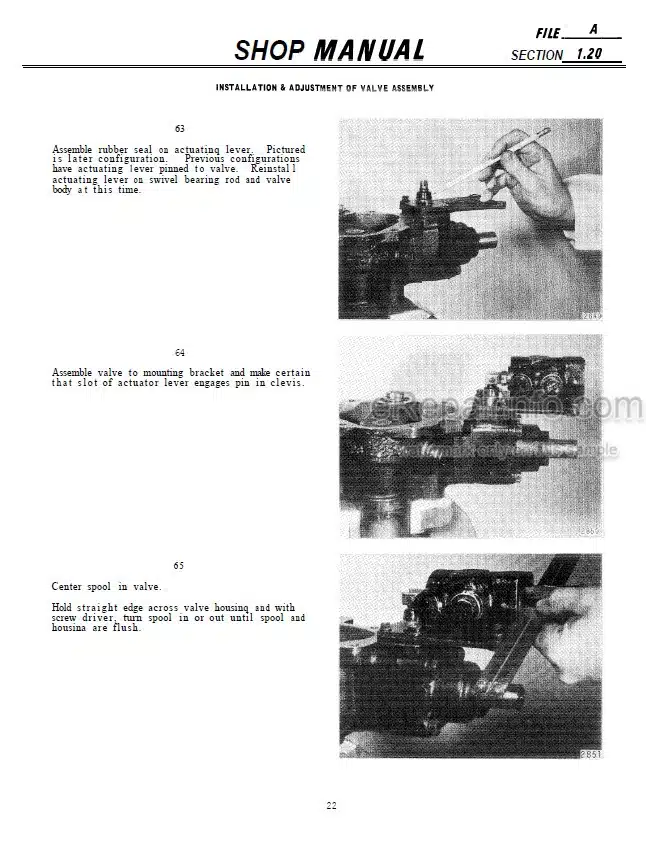
Steering Valve
Hydraulic Pump (Non-OV Type)
Control Valve
Lift Cylinder
Tilt Cylinder
Power Steering
Mast
Special Tool List
-STRUCTURE AND FUNCTION
Overview Of Service Data
Torque Converter
Transmission
Transmission Control Valve
Propeller Shaft
Differential
Final Drive
Steering Axle
Master Back, Master Cylinder
Wheel Brake
Parking Brake
Hydraulic Pump
Power Steering Cylinder
Lift Cylinder
Tilt Cylinder
Mast
Power train
Torque converter/Transmission control valve
Work equipment control valve
Hydraulic circuit diagram
Blake system
Master back, master cylinder
Assembly drawings
-ASSEMBLY DRAWINGS
Accelerator Pedal
Brake Inching Pedal
Parking Brake
Torque Converter
Torqflow Transmission
Differential
Front Axle
Steering Axle
Brake Piping
Work Equipment, Hydraulic Piping Diagrams
Mast
Electrical
Electrical Circuit Diagram
Speedometer (Option)
-TROUBLESHOOTING
Engine
Diesel Engine
Gasoline Engine
Electrical System
Torqflow System
Steering System
Brake System
Hydraulic System
-CONVERSION TABLE
Millimeters To Inches
Inches To Millimeters
Cubic Meters To Cubic Yards
Cubic Yards To Cubic Meters
Liter To US Gallon
US Gallon To Liter
Liter To US Gallon
US Gallon To Liter
Kilogram To Pound
Pound To Kilogram
KG/CM2 To LB/IN2
KGM To FT LB
Temperature
What you get
You will receive PDF file with high-quality manual on your email immediately after the payment.

Reviews
There are no reviews yet