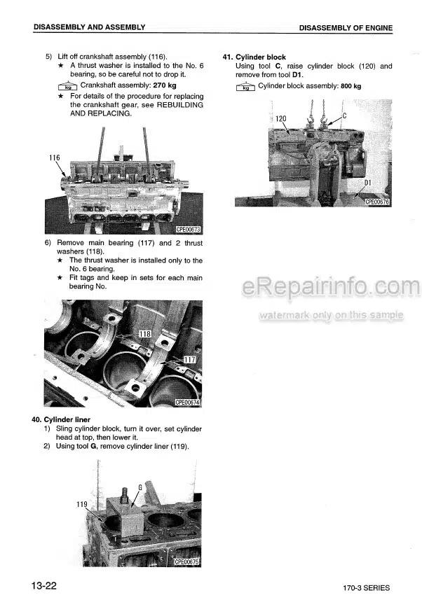
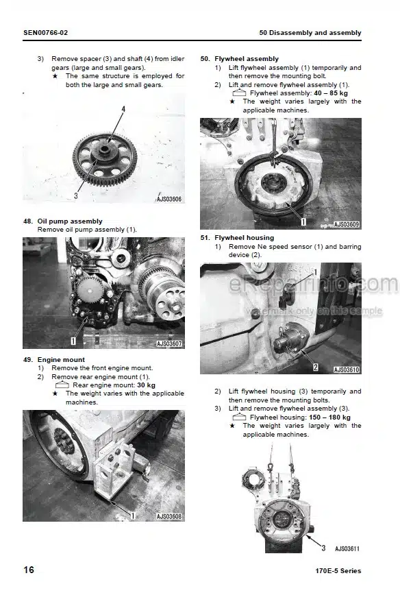
Factory Shop Manual For Komatsu Hydraulic Mining Shovel. Manual Contains Illustrations, Instructions, Diagrams For Step By Step Remove And Install, Assembly And Disassembly, Service, Inspection, Repair, Troubleshooting, Tune-Ups.
Format: PDF
Language: English
Pages: 497
Number: SMPC30006219 (july 2006)
Bookmarks: Yes
Wiring Diagrams: Yes
Hydraulic Diagrams: Yes
Model
Komatsu Hydraulic Mining Shovel
PC3000-6
SN 6219
Contents
-INTRODUCTION
Contents Of Binder
Foreword
Explanation Of Abbreviations
-SAFETY
Safety Instructions
General Precautions
Preparations For Work
Precautions During Work
-SPECIFICATIONS
Lifting Gears
Standard Tightening Torque Chart
Conversion Table
Explanation Of Abbreviations
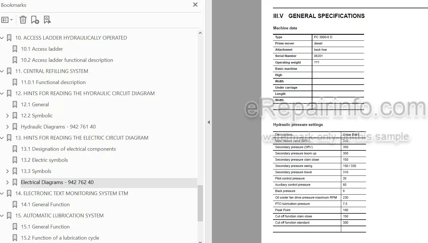
General Specifications
-MAIN ASSEMBLY GROUPS
General Layout
Superstructure
Power House
Hydraulic Oil Reservoir
Hydraulic Oil Cooler
Fuel Tank (Fuel Reservoir)
Counter Weight
Cab Support
Operators Cab
Control Blocks
Swing Gears
Under Carriage
-DRIVE
Prime Drive Assembly
Engine And Gearbox Mount
Torque Supports
Radiator Fan Drive Assy.
Pump Distributor Gearbox (PTO)
Coupling
Air Filter
-HYDRAULIC OIL RESERVOIR
Hydraulic Oil Reservoir
Return And Leak Oil Filter
Breather Filter
Location Of Electrical Components
-HYDRAULIC OIL COOLING
General
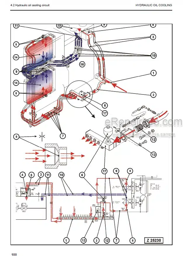
Hydraulic Oil Cooling Circuit
Back Pressure Valve Adjustment
Fan Drive
Cooler Fan Drive Adjustment
-CONTROLLING
Pilot Pressure Supply And Adjustment
Slew Brakes
Travel Parking Brake
Check Of The Pilot Control Logic
-COMPONENTS
Main Control Block And Valve Arrangement
Distributor Manifold
Main Control Block
Compact Valve Blocks
Compact Valve Blocks
Auxiliary Gear Pumps
Hydraulic Cylinder
Swing Ring
-MAIN HYDRAULIC PUMPS AND PUMP REGULATION
General
Main Pump Operating Principles
Main Pump Checks And Adjustments
Electronic Pump Regulation
Trouble Shooting Pump And Pump Regulation
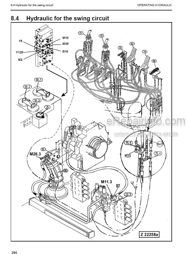
-OPERATING HYDRAULIC
General Layout
Floating Function Of Boom And Stick Only FSA
Check And Adjustments For MRV’s And SRV’s
Hydraulic For The Swing Circuit
Travel Circuit
-TRACK TENSION SYSTEM
General Layout
Track Tensioning Function
Truck Tensioning Adjustment
-ACCESS LADDER HYDRAULICALLY OPERATED
Access Ladder
Access Ladder Functional Description
-CENTRAL REFILLING SYSTEM
Functional Description
-HINTS FOR READING THE HYDRAULIC CIRCUIT DIAGRAM
General
Symbolic
Hydraulic Diagrams
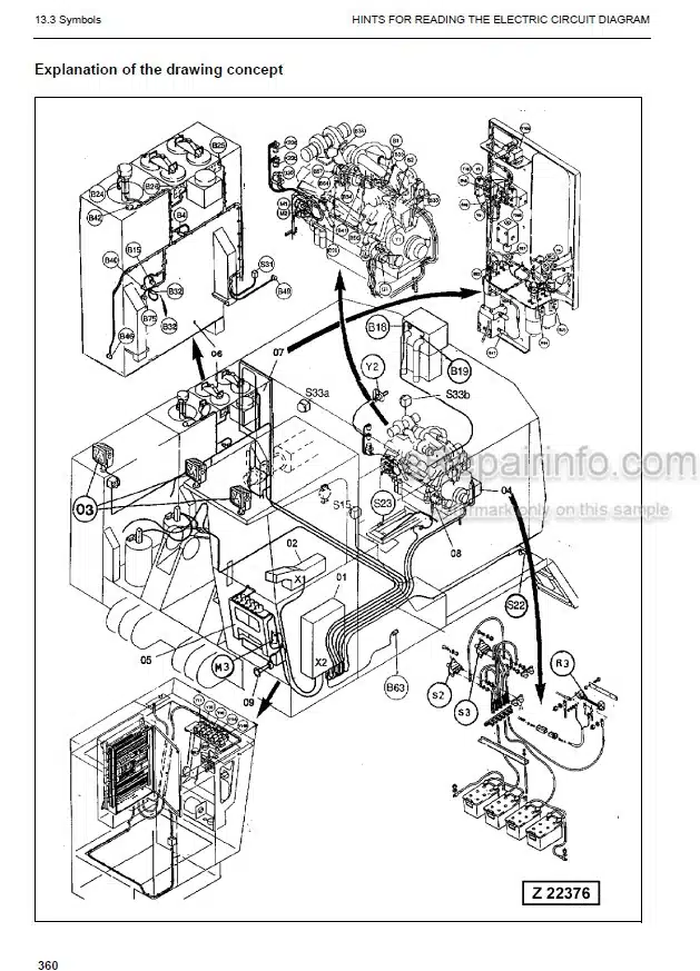
-HINTS FOR READING THE ELECTRIC CIRCUIT DIAGRAM
Designation Of Electrical Components
Electric Symbols
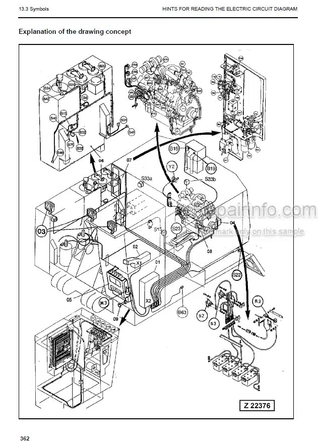
Symbols
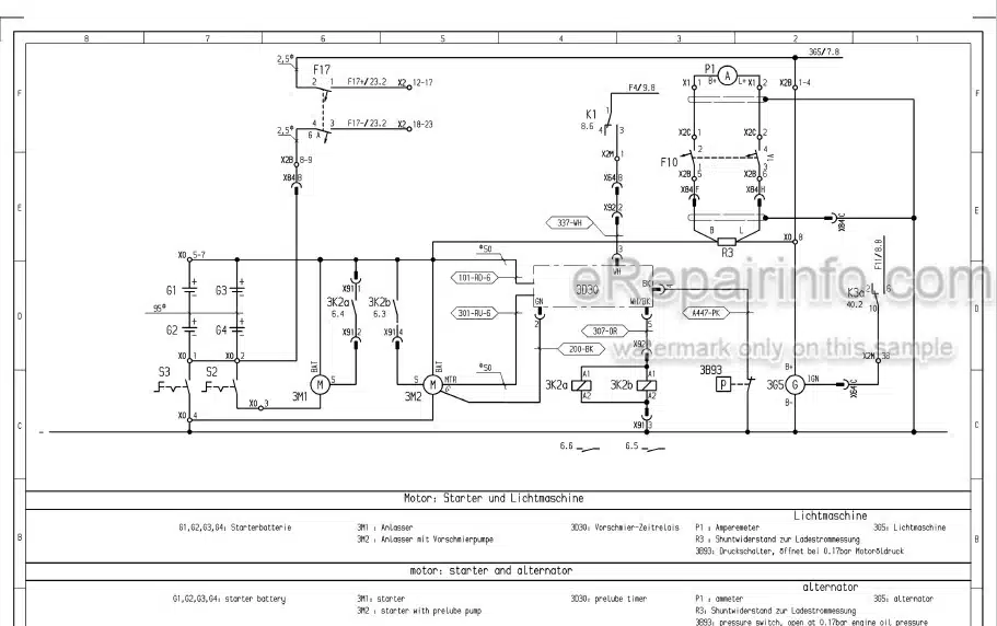
Electrical Diagrams
-ELECTRONIC TEXT MONITORING SYSTEM ETM
General Function
-AUTOMATIC LUBRICATION SYSTEM
General Function
Function Of A Lubrication Cycle
Lubrication Pump Drive
Lubrication Pump
Lubricant Injector (Metering Valve)
End Line Pressure Switch
Lubricant In Line Filter
Lubricant Level Sensor
Lubrication System Function And Controlling
Adjustment Of The Lubrication System With ETM
Trouble Shooting Lubricating System
What you get
You will receive PDF file with high-quality manual on your email immediately after the payment.
Reviews
There are no reviews yet