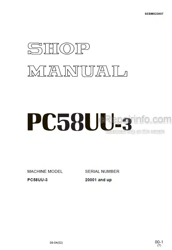
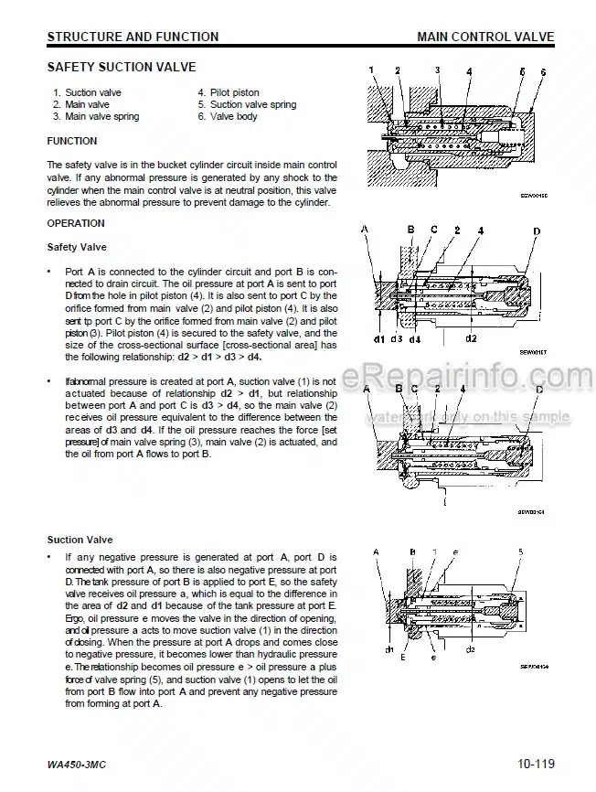
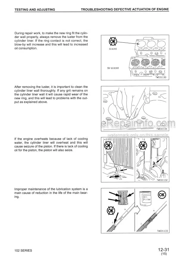
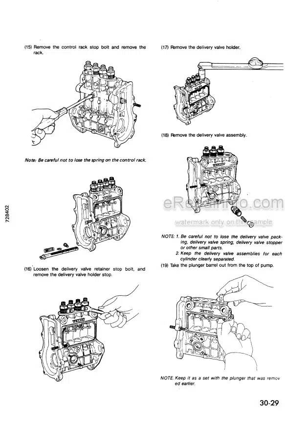
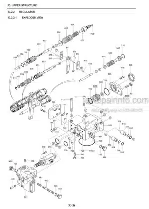
Factory Shop Manual For Komatsu Excavator. Manual Contains Illustrations, Instructions, Diagrams For Step By Step Remove And Install, Assembly And Disassembly, Service, Inspection, Repair, Troubleshooting, Tune-Ups.
Format: PDF
Language: English
Pages: 528
Number: SEBM023907 (august 2004)
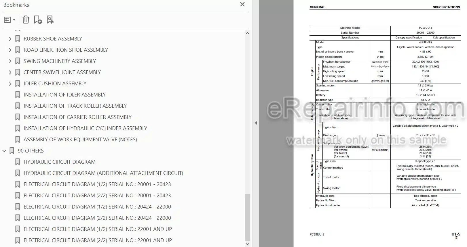
Bookmarks: Yes
Searchable: Yes
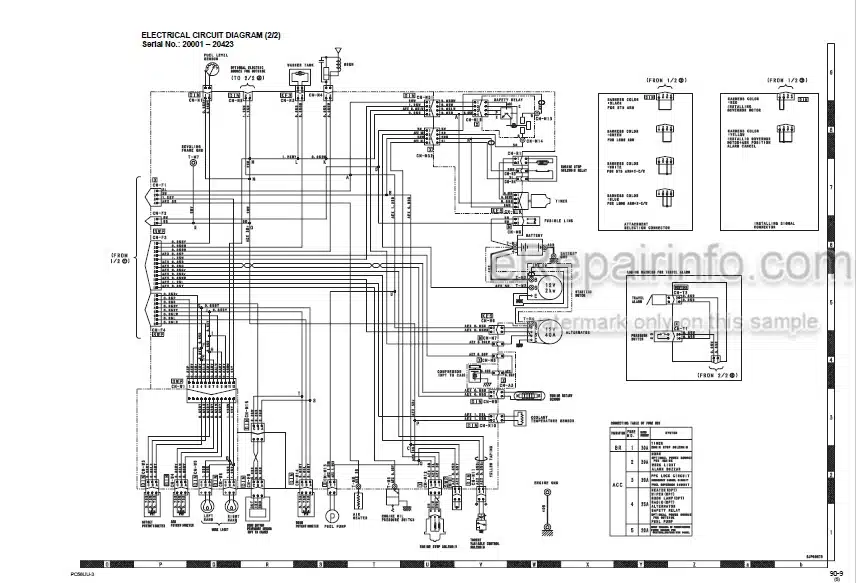
Wiring Diagrams: Yes
Hydraulic Diagrams: Yes
Model
Komatsu Excavator
PC58UU-3
Serial No. 20001 and up
Contents
-SAFETY
Safety Notice
-FOREWORD
General
How To Read The Shop Manual
Hoisting Instructions
Method Of Disassembling, Connecting Push-Pull Type Coupler
Coating Materials
Standard Tightening Torque
Electric Wire Code
Conversion Tables
Units
-GENERAL
General Assembly Drawing
Work Equipment Range Drawing
Specifications
Weight Table
List Of Lubricants And Coolant
-STRUCTURE, FUNCTION AND MAINTENANCE STANDARD
PTO
Cooling System
Power Train
Swing Circle
Swing Machinery
Track Frame, Idler Cushion
Idler
Track Roller
Carrier Roller
Sprocket
Track Shoe
Hydraulic Equipment Layout Drawing
Hydraulic Tank And Filter
Hydraulic Pump
Control Valve
CLSS
Center Swivel Joint
Travel Motor
Swing Motor
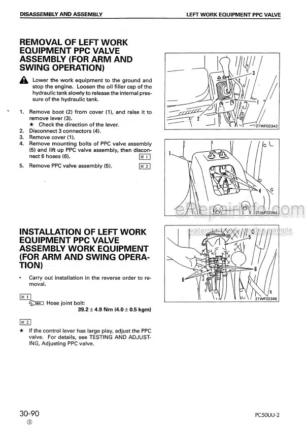
Travel PPC Valve
PPC Valve
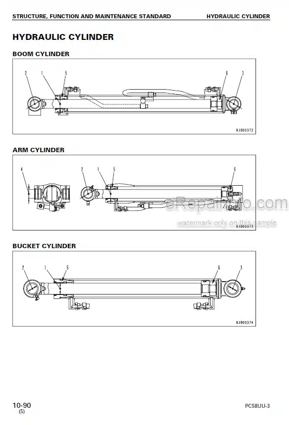
Hydraulic Cylinder
Solenoid Valve
Multi Control Valve
Work Equipment
Air Conditioning Piping
Engine Control
Electrical Control System
Electrical System
Monitor System
-TESTING AND ADJUSTING
Standard Value Table
Testing And Adjusting
Troubleshooting
-DISASSEMBLY AND ASSEMBLY
Method Of Using Manual
Precautions When Performing Operation
Special Tool List
Engine And Work Equipment Pump Assembly
Center Swivel Joint Assembly
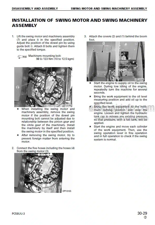
Swing Motor And Swing Machinery Assembly
Revolving Frame Assembly
Swing Circle Assembly
Rubber Shoe Assembly
Road Liner, Iron Shoe Assembly
Swing Machinery Assembly
Center Swivel Joint Assembly
Idler Cushion Assembly
Installation Of Idler Assembly
Installation Of Track Roller Assembly
Installation Of Carrier Roller Assembly
Installation Of Hydraulic Cylinder Assembly
Assembly Of Work Equipment Valve (Notes)
-OTHERS
Hydraulic Circuit Diagram
Hydraulic Circuit Diagram (Additional Attachment Circuit)
Electrical Circuit Diagram (1/2) Serial No.: 20001 – 20423
Electrical Circuit Diagram (2/2) Serial No.: 20001 – 20423
Electrical Circuit Diagram (1/2) Serial No.: 20424 – 22000
Electrical Circuit Diagram (2/2) Serial No.: 20424 – 22000
Electrical Circuit Diagram (1/2) Serial No.: 22001 And Up
Electrical Circuit Diagram (2/2) Serial No.: 22001 And Up
What you get
You will receive PDF file with high-quality manual on your email immediately after the payment.
Reviews
There are no reviews yet