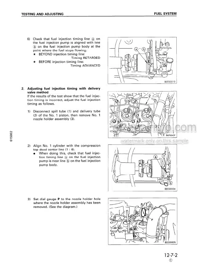
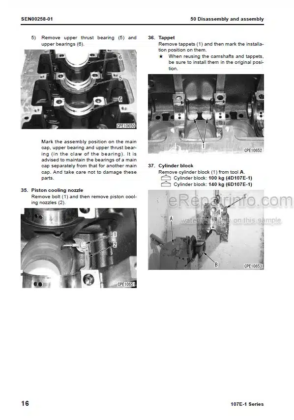
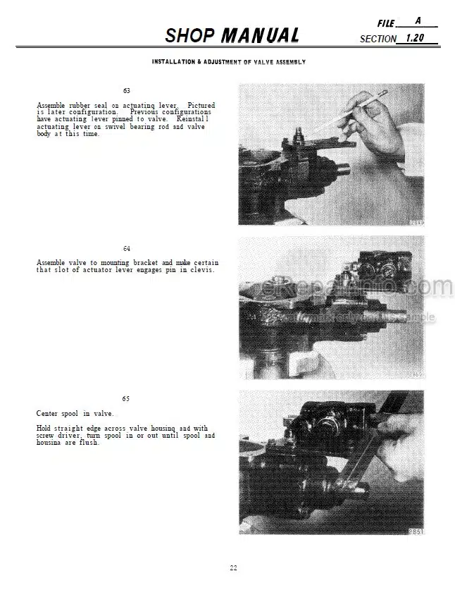
Factory Shop Manual For Komatsu Wheel Excavator. Manual Contains Illustrations, Instructions, Diagrams For Step By Step Remove And Install, Assembly And Disassembly, Service, Inspection, Repair, Troubleshooting, Tune-Ups.
Format: PDF
Language: English
Pages: 410
Number: EEBM000106 (march 1995)
Wiring Diagrams: Yes
Hydraulic Diagrams: Yes
Model
Komatsu Wheel Excavator
PW170-5K
SN K20001 And Up
Contents
FOREWORD
-STRUCTURE AND FUNCTION
General View
PTO
Powertrain
Transmission
Axle
Swing Circle
Swing Machinery
Steering Train
Fuel Tank
Hydraulic Tank
Hydraulic Circuit Diagram
Hydraulic Pump
LH 6-Spool Control Valve
RH 6-Spool Control Valve
Swing Motor
Swivel Joint
Travel Motor
PPC Valve
Accumulator
Safety Lock Valve
Solenoid Valve
Shuttle Valve
Boom Holding Valve
Hydraulic Cylinder
Work Equipment
Suspension Lock Cylinder
Stabilizer Cylinder
Dozer Blade Cylinder
Air Circuit
Alcohol Injector
Unload Valve
Brake Lock Valve
Air Swivel Joint
Pressure Reducing Valve
Break Servo Cylinder
Air Chamber
Service Brake
Parking Brake
Engine Control System
PEMC System
EMACC (Electronic Monitor And Control Console)
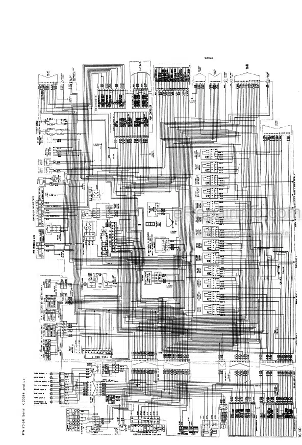
Electrical Wiring Diagram
Electrical Circuit Diagram
Others
-TESTING AND ADJUSTING
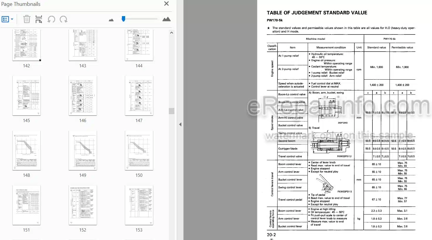
Table Of Judgment Standard Value
Standard Value Table For Electrical System
Tools For Testing, Adjusting, And Troubleshooting
Adjusting Travel Of Governor Motor Lever
Adjusting Engine Speed Sensor
Inspection Of Swing Circle Bearing Clearance
Testing And Adjusting Hydraulic Pressure
In Work Equipment Swing, Travel Circuit
Testing And Adjusting Charging Pump Pressure
Testing And Adjusting Main Pump Control Pressure
Measuring Stroke Of Servo Piston
Measuring Output Pressure Of PPC Valve
Adjusting PPC Valve
Testing PPC Shuttle Valve
Measuring Solenoid Valve Outlet Port Pressure
Testing Locations Causing Hydraulic Drift Of Work Equipment
Bleeding Air
Releasing Remaining Pressure In Hydraulic Circuit
Testing And Adjusting Toe-In
Adjusting Maximum Lock Angle Of Front Wheels
Adjusting Parking Brake
Bleeding Air From Brake Circuit
-DISASSEMBLY AND ASSEMBLY
Precautions When Carrying Out Operation
Special Tool List
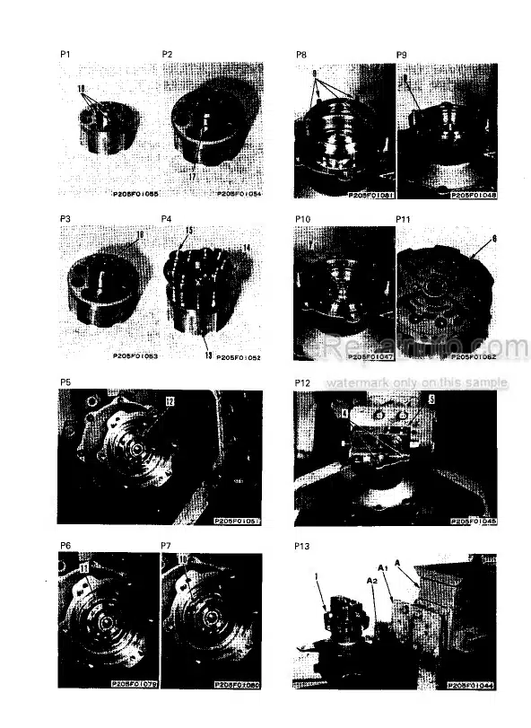
Weight Table
Tightening Torques And Standard Values Table3
Lubricant And Coolant Table
Hydraulic Cooler Assembly
Radiator, Hydraulic Cooler Assembly
Engine And Hydraulic Pump Assembly
PTO Assembly
Swivel Joint Assembly
Travel Motor
Rotary Group
Control Piston Seal
Swing Motor Assembly
Swing Machinery Assembly
Revolving Frame Assembly
Swing Circle Assembly
Charging Pump Assembly
Hydraulic Pump Assembly
Control Valve Assembly
Main Relief Valve Assembly
TVC Valve Assembly
CO – NC Valve Assembly
Servo Valve Assembly
Work Equipment PPC Valve Assembly
PPC Shuttle Valve Assembly
Boom Holding Valve Assembly
Boom Raise Cylinder Assembly
Boom Adjust Cylinder
Arm Cylinder Assembly
Bucket Cylinder Assembly
Dozer Blade Cylinder
Stabilizer Cylinder
Outrigger Assembly
Oscillating Axle Blocking Rams
Oscillating Axle Arm
Hydraulic Cylinder Assembly
Work Equipment Assembly
Bucket Assembly
Arm Assembly
Arm, Bucket Assembly
Pump Controller Assembly
Boom Assembly
Upper Boom Assembly (For 2PC-Boom)
Upper 8- Lower Boom (For 2PC-Boom)
Operator’s Cab Assembly
Counterweight
Engine Throttle Controller Assembly
Monitor Panel Assembly
Additional Monitor Panel Assembly
Travel Transfer Gearbox
Steering Axle
Rigid Axle
Steering Unit
Arm Rotation Motor Assembly
Work Equipment Assembly For Rotating Arm
Arm Assembly
Arm Swivel Joint Assembly
-MAINTENANCE STANDARD
Travel Brake Valve
Transmission
Swing Machinery
Swing Circle
Steering Pump
Steering Cylinder
Final Drive And Differential
King Pin And Knuckle
Wheel Brake
Parking Brake
Oscillation Lock Cylinder
LH 6-Spool Control Valve
RH 5-Spool Control Valve
Charging Pump And Relief Valve
Boom Holding Valve
Hydraulic Cylinder
Work Equipment
Arm Rotation Circle
Arm Swivel Joint
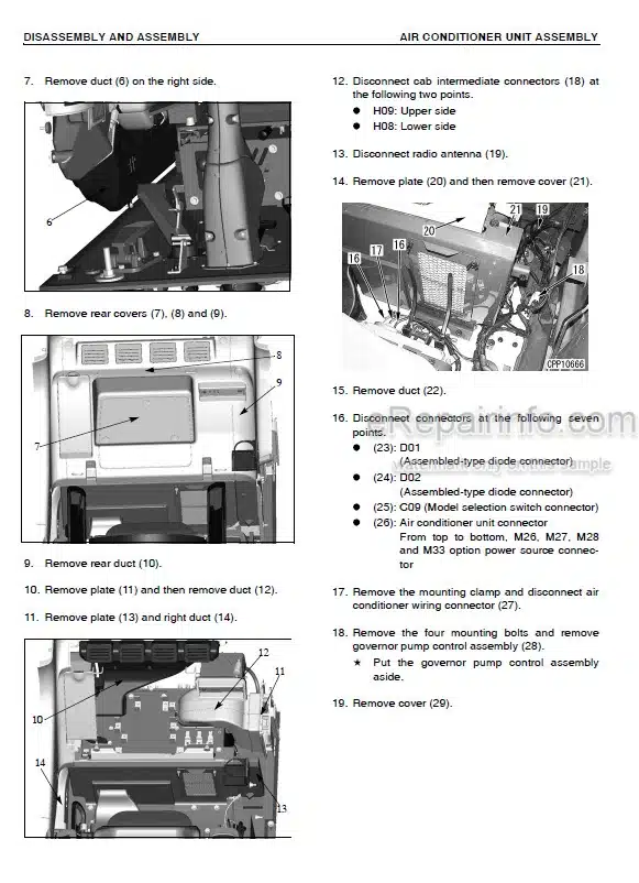
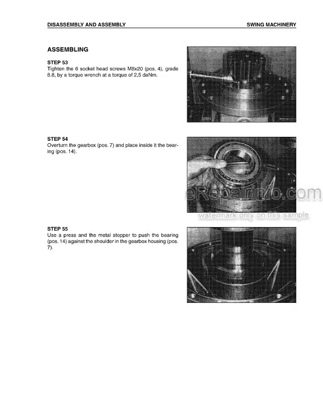
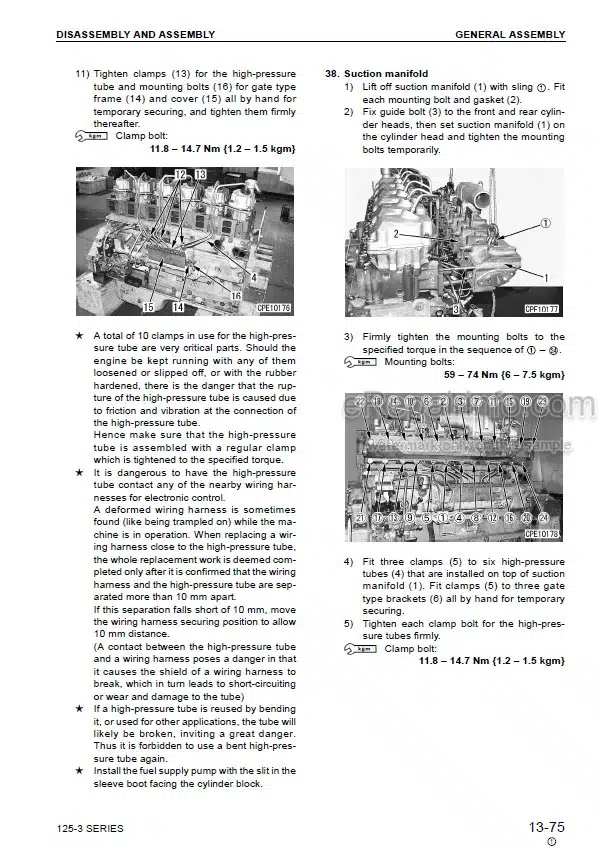
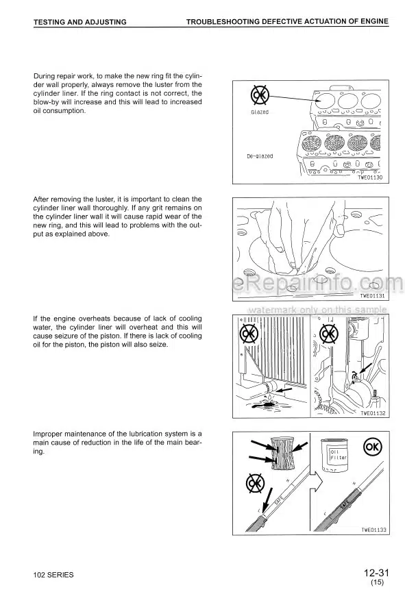
What you get
You will receive PDF file with high-quality manual on your email immediately after the payment.
Reviews
There are no reviews yet