


Factory Shop Manual For Komatsu Wheel Loader. Manual Contains Illustrations, Instructions, Diagrams For Step By Step Remove And Install, Assembly And Disassembly, Service, Inspection, Repair, Troubleshooting, Tune-Ups.
Format: PDF
Language: English
Pages: 780
Number: VEBM220100 (april 2004)
Bookmarks: Yes
Searchable: Yes
Wiring Diagrams: Yes
Hydraulic Diagrams: Yes
Model
Komatsu Wheel Loader
WA200-5H
SN H50051 And Up
WA200PT-5H
SN H60051 And Up
Contents
SAFETY
-FOREWORD
Safety Notice
General
How To Read The Shop Manual
Hoisting Instructions
Method Of Disassembling, Connecting Push-Pull Type Coupler
Coating Materials
Standard Tightening Torque
Electric Wire Code
Conversion Table
Units
-GENERAL
General Assembly Drawings
Specifications
Weight Table
List Of Lubricant And Coolant
-STRUCTURE, FUNCTION AND MAINTENANCE STANDARD
Engine Mount And Transfer Mount
Damper
Cooling System
Transfer Oil Cooler
Power Train
Power Train System Diagram
Drive Shaft (Propeller Shaft)
HST Hydraulic Piping Diagram
HST Pump
High-Pressure Relief Valve
Low-Pressure Relief Valve
HST Charge Pump
Speed-Related Valve (Da Valve)
High-Pressure Cut-Off Valve
HST Motor
EP Servo Valve
HA Servo Valve
Forward-Reverse Shuttle Valve
Transfer
Clutch Solenoid Valve
Axle
Differential
Limited-Slip Differential
Final Drive
Axle Mounting And Center Hinge Pin
Steering Piping
Steering Column
Priority Valve
Orbit-Roll Valve
2-Way Restrictor Valve
Cushion Valve
Steering Cylinder
Emergency Steering Piping
Emergency Steering Valve
Brake Piping
Brake Valve
Inching Valve
Charge Valve
Accumulator (For Brake)
Slack Adjuster
Brake
Parking Brake Control
Parking Brake
Hydraulic Piping
Work Equipment Lever Linkage
Hydraulic Tank
4-Gear Pump Unit
Accumulator (For PPC Circuit)
Lock Valve
Bypass Valve
Quick Coupler Valve
ECSS Valve
Accumulator (For ECSS)
Hydraulic Piping Of Cooling System
Cooling Fan Motor
Work Equipment Control Valve
Work Equipment PPC Valve
Attachment PPC Valve
Work Equipment Linkage
Bucket
Control Of Bucket Positioner, Boom Kick-Out, And Dump Speed
Work Equipment Cylinder
Air Conditioner
Machine Monitoring System
Machine Monitor
List Of Items Displayed On Monitor
Electrical System (HST Controller System)
HST Controller
Function Of Selecting Directional Selector Switch
Engine Start Circuit
Engine Stop Circuit
Preheating Circuit
Parking Brake Circuit
Electronically Controlled Suspension System
Sensors
-TESTING AND ADJUSTING
Standard Value Table
Testing And Adjusting
Troubleshooting
-TROUBLESHOOTING
Points To Remember When Troubleshooting
Sequence Of Events In Troubleshooting
Precautions When Carrying Out Maintenance
Check Before Troubleshooting
Categories, Procedure, And Method Of Using Troubleshooting Charts
Phenomena Considered To Be Failures And Troubleshooting No
Connection Table For Connector Pin Numbers
T-Adapter Table
Connector Types And Mounting Locations
Connector Layout Drawing
-DISASSEMBLY AND ASSEMBLY
Removal And Installation Of Fuel Injection Pump Assembly
Removal And Installation Of Nozzle Holder Assembly
Removal And Installation Of Cylinder Head Assembly
Removal And Installation Of Engine
Removal And Installation Of Radiator Assembly
Removal And Installation Of Air Aftercooler Assembly
Removal And Installation Of Hydraulic Oil Cooler Assembly
Removal And Installation Of Cooling Fan And Fan Motor Assembly
Removal And Installation Of Fuel Tank Assembly
Removal And Installation Of Transfer Assembly
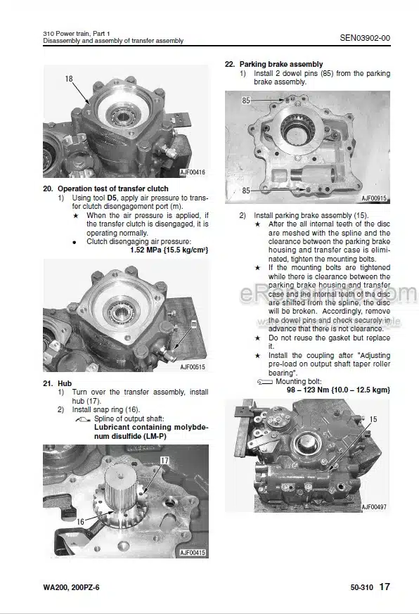
Disassembly And Assembly Of Transfer Assembly
Removal And Installation Of Parking Brake Assembly
Disassembly And Assembly Of Parking Brake Assembly
Removal And Installation Of Front Axle Assembly
Removal And Installation Of Rear Axle Assembly
Disassembly And Assembly Of Axle Housing Assembly
Disassembly And Assembly Of Differential Assembly
Removal And Installation Of HST Pump And 4-Gear Pump Assembly
Removal And Installation Of HST Motor Assembly
Removal And Installation Of Work Equipment Control Valve Assembly
Removal And Installation Of Travel Damper Valve Assembly
Removal And Installation Of Hydraulic Tank
Removal And Installation Of Work Equipment Assembly
Disassembly And Assembly Of Hydraulic Cylinder Assembly
Removal And Installation Of Operator’s Cab Assembly
Removal And Installation Of Operator’s Cab Glass (Stuck Glass)
Removal And Installation Of Center Hinge Pin
Removal And Installation Of Counterweight
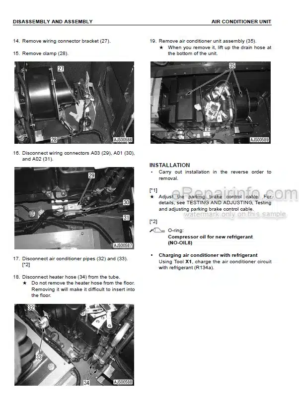
Removal And Installation Of Air Conditioner Unit Assembly
Removal And Installation Of Air Conditioner Compressor Assembly
Removal And Installation Of Monitor Panel
How To Read This Manual
Precautions When Performing Operation
Special Tool List
Sketches Of Special Tools
-OTHERS
Hydraulic Circuit Diagram
Electrical Circuit Diagram
What you get
You will receive PDF file with high-quality manual on your email immediately after the payment.


Reviews
There are no reviews yet