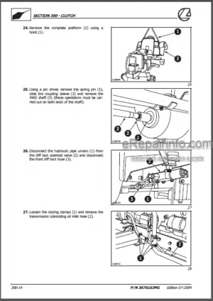
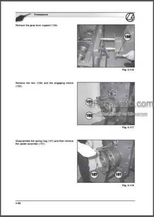
Factory Training Repair Manual For Landini Mistral 40 45 50. Tons of illustrations, instructions, diagrams for step by step remove and install, assembly and disassembly, service, inspection, repair, troubleshooting, tune-ups.
Format: PDF
Language: English
Pages: 462
Number: 3651914M3
Bookmarks: No
Searchable: Yes
Wiring Diagrams: Yes
Hydraulic Diagrams: Yes
Models
Mistral 40
Mistral 45
Mistral 50
Contents
-GENERAL INFORMATION
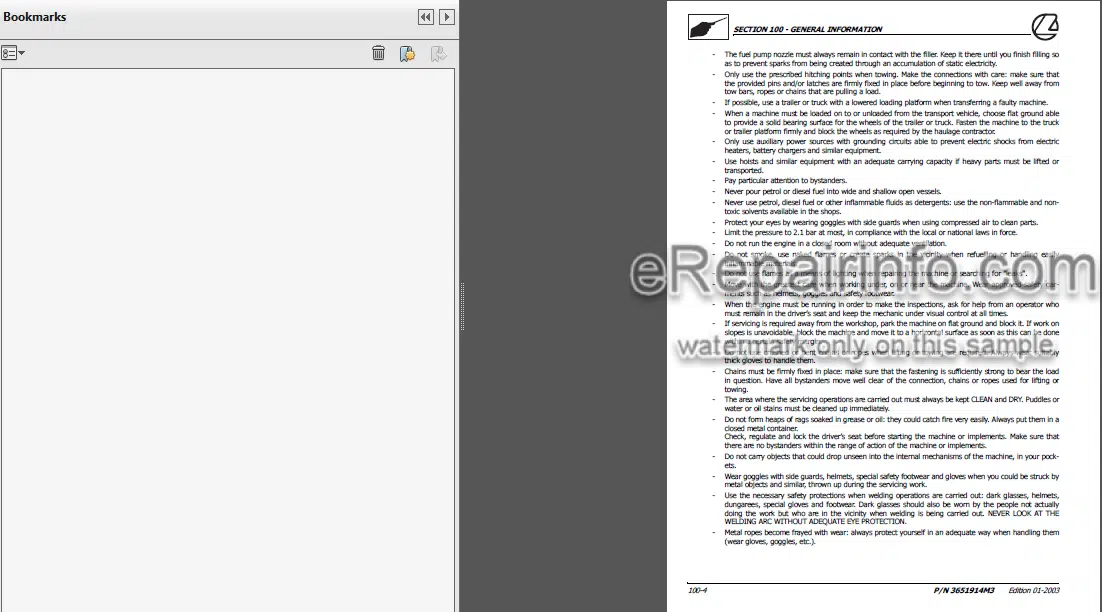
Safety Notes
General Instructions
Symbols
Danger Signs
Sealing And Fixing Sealants
Lubricants And Fuels
Conventional Units Of Measurement
Standard Driving Torque Values
-ENGINE
General Features
Main Specifications
Driving Torque Values
Specific Equipment
Sections
Lubrication Cooling And Fuelling Circuit Diagrams
Engine Troubleshooting
Engine Splitting And Remounting
Compression Test
Engine – Overhaul
Injector Nozzle And Injection Pressure Measuring And Monitoring
Injection Timing Adjustment And Monitoring
Idling Rate Adjustment (Minimum And Maximum)
How To Check The Cooling System And Radiator To Find Leaks
Sensor Inspection
Cylinder Head Inspections, Measurements And Repairs
Crankcase And Cylinder Liner Inspections, Measurements And Repairs
Rocker Arm Inspections, Measurements And Repairs
Piston And Piston Ring Inspections, Measurements And Repairs
Connection Rod Inspections, Measurements And Repairs
Camshaft Inspections, Measurements And Repairs
Drive Shaft Inspections, Measurements And Repairs
Gear Inspections, Measurements And Repairs
Oil Pump Inspections, Measurements And Repairs
Yanmar Injection Pump
Injection Pump – Overhaul
Regulator Unit – Overhaul
-CLUTCH
General Specifications Of The Lx 9”/9” Clutch
Driving Torque Values
Specific Equipment
Sections
Troubleshooting For The Clutch Assembly
Where The Sealant Is Applied For The Clutch Housing On The Transmission Housing
Clutch Splitting-Remounting
Control Adjustment Gearshift Clutch
Control Adjustment Power Take-Off Clutch
-(12 + 12) AND (16 + 16) MECHANICAL GEARBOX
Main Specifications Of The Gearbox And Final Drive
Main Specifications Of Reverse Shuttle
Main Specifications Of The Supplementary Final Drive (16 + 16 Version)
Driving Torque Values
Sections
Description And Operation
Troubleshooting For The Gearbox, Creeper And Reverse Shuttle
Troubleshooting For The Creeper (16-16 Version)
Where The Sealant Is Applied For The Gearbox-Rear Transmission Housing
Gearbox Transmission Housing Splitting-Remounting
Gearbox Transmission Housing – Overhaul
Clutch Housing – Overhaul
-REAR DIFFERENTIAL HOUSING
Main Specifications Of The Bevel Gear Pair And Differential
Driving Torque Values
Sections
Description And Operation
Troubleshooting For The Bevel Gear Pair And Differential
Troubleshooting For The Side Final Drives
Where The Sealant Is Applied For The Gearbox-Rear Transmission Housing
Rear Transmission Housing – Overhaul
Right Or Left Side Final Drive Housing-Assembly Splitting Remounting
Driving Wheel Shaft – Overhaul
Bevel Gear Pair Adjustment
-FRONT AXLE
Main Specifications
Driving Torque Values
Specific Equipment
Sections
Description And Operation
Troubleshooting For The Front Axle Diff Lock Device
Front Axle
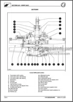
Front Axle Differential And Bevel Gear Pair Support
Front Bevel Gear Pair – Overhaul
Front Diff Lock – Overhaul
Wheel Hub – Overhaul
Front Final Drive – Splitting Remounting
Front Final Drive – Overhaul
Axle Steering Cylinder – Splitting Remounting
-POWER TAKE-OFF
Main Specifications
Driving Torque Values
Sections
Description And Operation
Troubleshooting For The Mechanically Engaged Power Take-Off
Where The Sealant Is Applied On The Power Take-Off Cover
Mechanically Engaged Power Take-Off Overhaul
-HYDRAULIC CIRCUITS – REAR POWER LIFT
Main Specifications – Rear Hydraulic Power Lift
Specific Equipment
Sections And Perspective Views
Description Of The Operating Mode Of The Hydraulic Power Lift
Description Of The Operating Mode Of The Hydraulic Power Lift’S Valve System
Hydraulic Power Lift’S Valve System – Splitting-Remounting
Power Lift’S Valve System – Overhaul
Valve System Of The Hydraulic Power Lift – Hydraulic Tests
Power Lift – Adjustments
Hydraulic Power Lift – Operating Pressure Test
-HYDRAULIC CIRCUITS – AUXILIARY CONTROL VALVES
Main Specifications
Sections
Description And Operation
-STEERING SYSTEM
Main Specifications
Sections And Exploded Views
Description And Operation
Operating Pressure Tests
-BRAKES
Main Specifications
Driving Torque Values
Sections
Description And Operation
Brake System Troubleshooting
Where The Sealant Is Applied On The Brake Assembly And Side Final Drives On The Transmission Housing
Right Or Left Brake Splitting-Remounting
Adjustments
-ELECTRICAL SYSTEM – INSTRUMENTS
Instruments
Transmitters, Sensors And Switches
Maintenance
-ELECTRICAL SYSTEM – COMPONENTS
Control Panel With Analogue Instrument
Light Switch
Hazard Light Switch
Rotating Beam Switch
Ignition Switch
Diff Lock Control Button
Maintenance
-ELECTRICAL SYSTEM – IGNITION SYSTEM
Technical Specifications
Description And Operation
Troubleshooting
Tests
-ELECTRICAL SYSTEM – RECHARGING SYSTEM
Technical Specifications
Description And Operation
Tests And Troubleshooting
Alternator. Splitting – Remounting
-ELECTRICAL SYSTEM – BATTERY
Technical Specifications
Description And Operation
Battery Splitting – Remounting
Maintenance And Battery Inspection
Common Causes Of Battery Faults
-ELECTRICAL SYSTEM – ELECTRICAL CIRCUITS
Electrical System Components
Electrical System Components (Continued)
Tractor – Component Locations
Control Panel – Component Locations
Locations Of Fuses And Relays
Fuses
Maxi Fuses
Relays
Symbols Used In The Electrical Circuits
Colour Codes Of The Electrical Wires
Identification Code Of The Wiring Diagrams And Connections
Main Wiring And Wiring Diagrams
Main Wiring
Main Front Wiring (Diagram Of Engine And Lights)
Starting And Recharging Diagram – Seven Pin Socket (Diagram A)
Electric Diagram Of Side-Lights, Driving Beams, Dipped Beams, Licence Plate Light And Instrument Light (Diagram B)
Diagram Of Hazard Lights And Turn Indicator Blinkers – Horn (Diagram C)
Main Rear Wiring
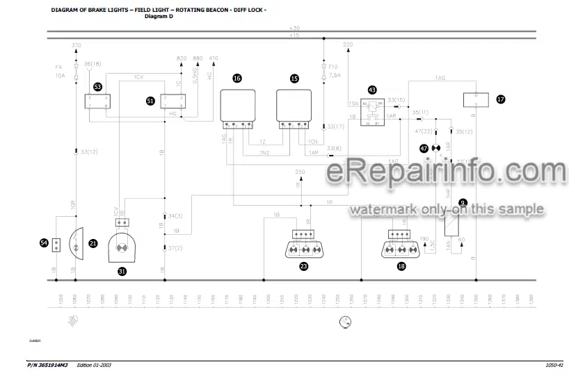
Electric Diagram Of Brake Lights – Field Light – Rotating Beacon – Diff Lock (Diagram D)
Diagram Of Sensors And Transmitters (Diagram E)
What you get
You will receive PDF file with high-quality manual on your email immediately after the payment.




Reviews
There are no reviews yet