Factory Service Manual For Liebherr Wheel Loader. Manual Contains Illustrations, Instructions, Diagrams For Step By Step Remove And Install, Assembly And Disassembly, Service, Inspection, Repair, Troubleshooting, Tune-Ups.
Format: PDF
Language: English
Pages: 721
Issued: 1987-1993
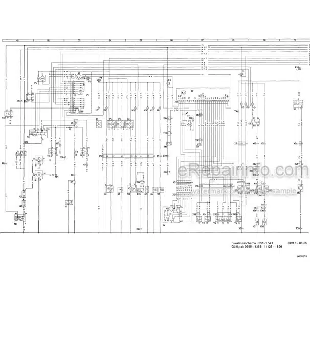
Wiring Diagrams: Yes
Hydraulic Diagrams: Yes
Model
Liebherr Wheel Loader
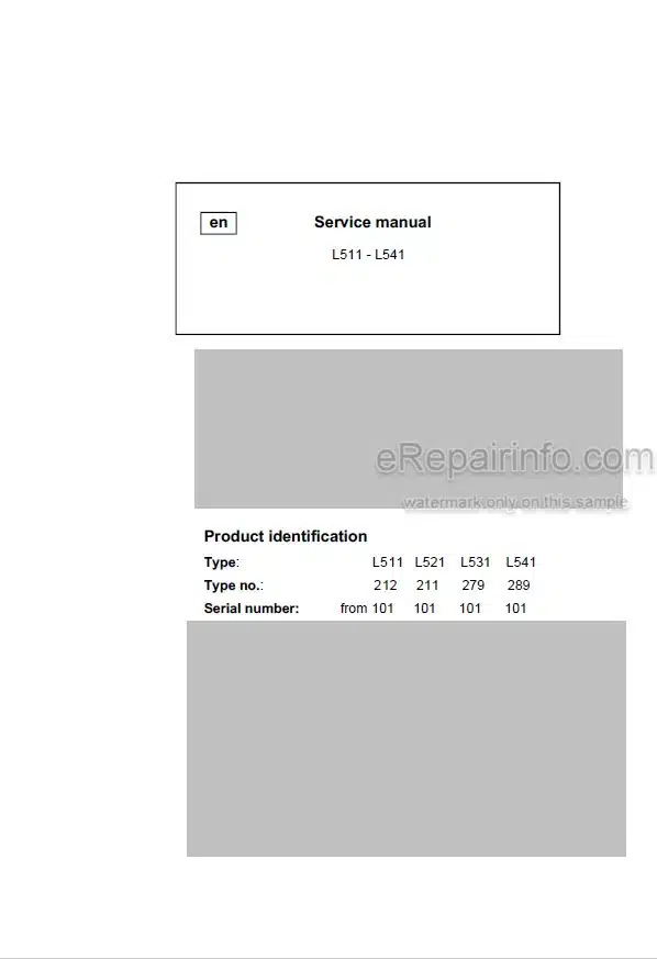
L511
L521
L531
L541
Serial No. from 101
Contents
-SAFETY INFORMATION
-GENERAL
Conversion Chart
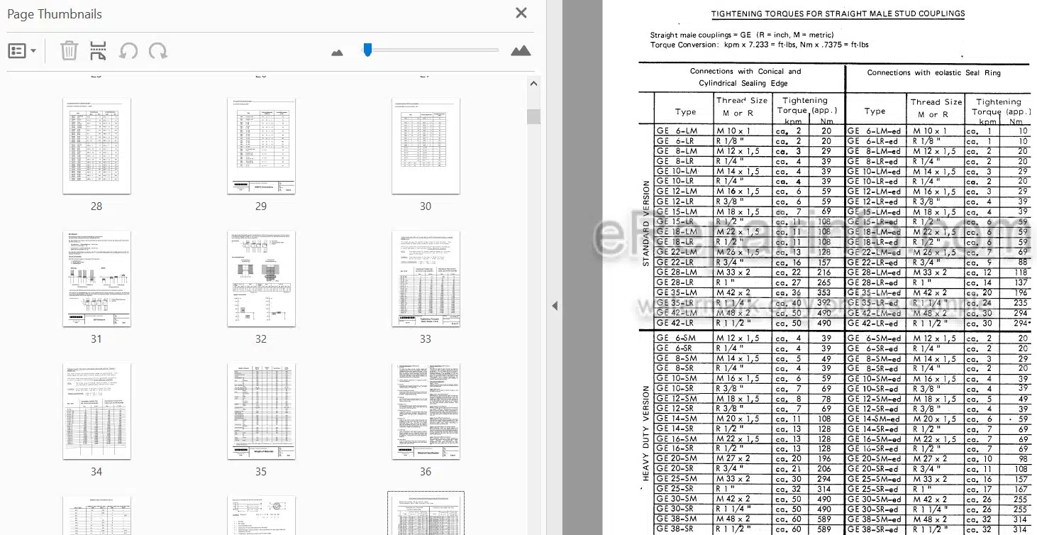
Tightening Torques
ISO
Material Classification
-SPECIAL TOOLS
-REPAIR WELDING
-LUBRICANTS
General
Lubrication And Operating Fluids
Lubrication Chart
-TECHNICAL DATA AND INSPECTION SCHEDULES
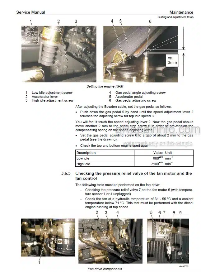
Adjustment Checklist
Technical Data
Inspection Shedule
Traction Diagram
Maintenance And Inspection
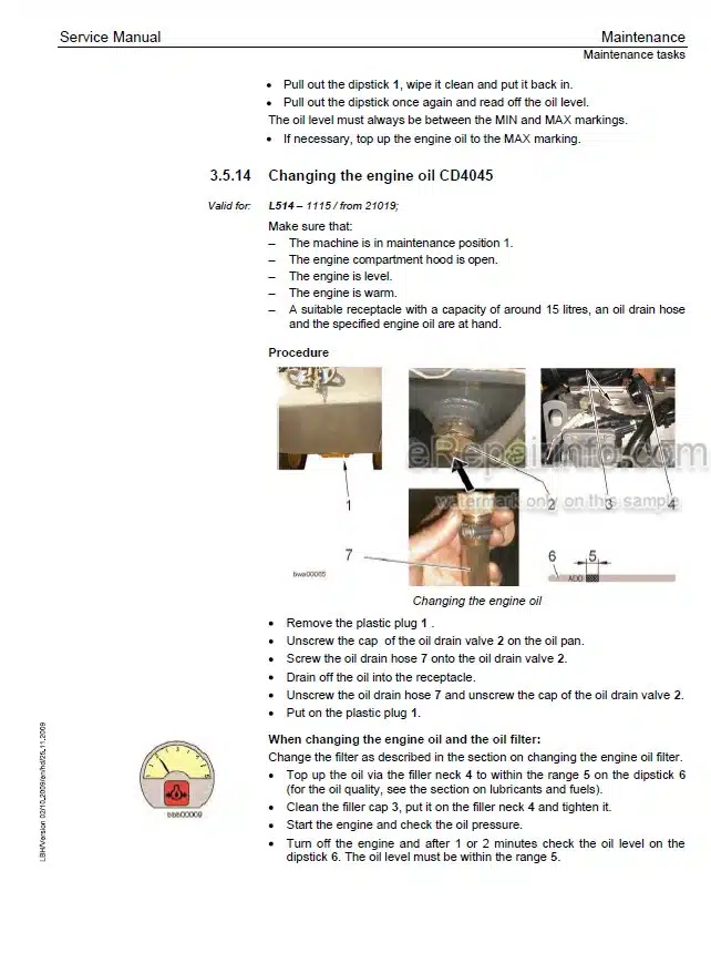
-DIESEL ENGINE/ CLUTCH
Liebherr Engine
Deutz Engine
Solenoid / Engine Shut Off
Clutch
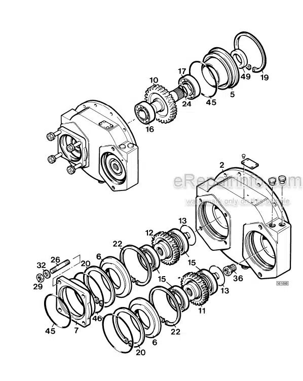
-PUMP DISTRIBUTOR GEAR
Description With Drawing Of The Gear Box
-TRAVEL HYDRAULIC
Operating Pressure
Travel Hydraulic System
Hydraulic Pump A 4 V
Block Curve / Travel System
Hydraulic Motor A 6 V M
Hydraulic Motor A6 V
Regulator Valve
Replenishing Pressure Relief Valve
Crossover Relief Valve
Pressure Cutoff Valve
Inching Valve
Towing Procedure
-WORKING HYDRAULIC
Working Pressure
Working Hydraulic-Appliance
Variable Displacement Pump A10V
Variable Displacement Pump A7V
Pump Performance Diagram
Control Valve-Block
General Information, Leakage Oil Information
Control Valve-Block NG 16/NG 22
Control Valve-Block NG 22
Pressure Relief-Valve Direct Controlled
Pressure Relief-Valve Pilot Controlled
Pressure Relief-Valve With Suction Valve Function
Throttle – Check Valve
Bleeder Valve
Thermostatic Valve
Pilot Control
Pilot Control Valve
Hydraulic Cylinder
-ELECTRICAL SYSTEM
Electrical System
Battery
Starter
Alternator
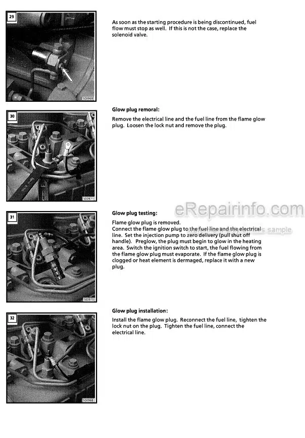
Pre-Heating System – Glow Plug
Electrical System
Instrument / Tachometer / Diode Board
Proximity Switch
-HEATING AND VENTILATION SYSTEM
Heating And Ventilation System
-POWERSHIFT TRANSMISSION
Shifting Unit
Troubleshooting
Bypass – Valve
-AXLES/TYRES
Axles – General
Differential
Wheel Head
-STEERING
General Data
Hydraulic Steering System
Valve Block
Servostat
Servo Control Valve
Steering Cylinder
-BRAKES
General Information
Hydraulic Brake System
Cut Off Valve
Service Brake Valve
Parking Brake Valve
-MAIN FRAME/CAB
Description of Removal / Installation of Articulation and Oscillating Axle
Description and Construction of Cab
-LIFT ARMS
Lift Arms
Special Lift Arms
-SPECIAL ATTACHMENT
Attachment – Snow Remover
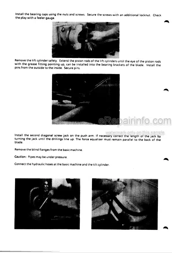
Attachment – Front section / Manual control
Parallel Motion
Hydraulic Quick Change Coupling
What you get
You will receive PDF file with high-quality manual on your email immediately after the payment.
Reviews
There are no reviews yet