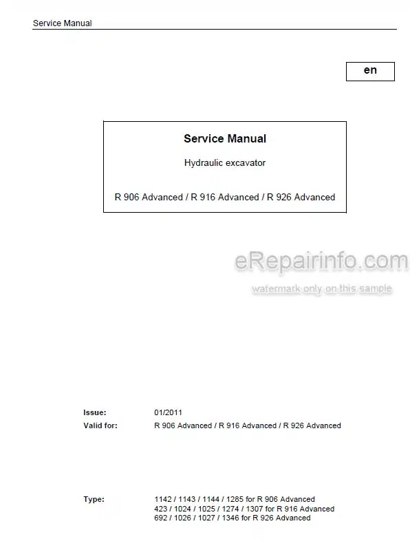
Factory Service Manual For Liebherr Hydraulic Excavator. Manual Contains Illustrations, Instructions, Diagrams For Step By Step Remove And Install, Assembly And Disassembly, Service, Inspection, Repair, Troubleshooting, Tune-Ups.
Format: PDF
Language: English
Pages: 681
Issued: january 2011
Bookmarks: Yes
Searchable: Yes
Wiring Diagrams: Yes
Hydraulic Diagrams: Yes
Model
Liebherr Hydraulic Excavator
R906
R916
R926
Advanced
Contents
-GENERAL INFORMATION
Safety Instructions, Signs On The Machine
Tightening Torques
Installations For Pistons And Piston Nuts By Hydraulic Cylinders
Assembly Instruction For Piston Rod Bearings With External Threads (Hydraulic Cylinders)
Lubricants And Operating Fluids
-TOOLS
Special Tools For Maintenance And Repair
Special Tools For Liebherr Diesel Engines D 9341 D 936
Special Tool For The Hydraulic System
Service Case Advanced
Special Tools For Electrical Connectors
Special Tools For Gears
Common Tools
Measuring Tool For Spool Travel
Mounting Tools For Hydraulic Cylinders
-TECHNICAL DATA / MAINTENANCE GUIDELINES
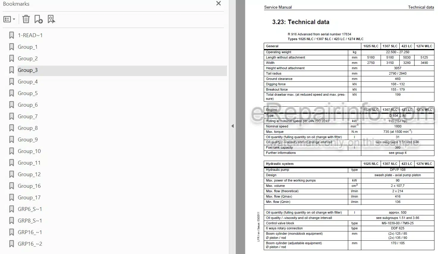
Technical Data
Control And Maintenance Chart
Lubrication Chart
-ENGINE
Technical Data for LIEBHERR Engine Type: D 934 S A6
-COUPLING / SPLITTERBOX
Coupling
Splitterbox
Remove, Disassembly, Assembly And Installation Of Splitterbox
-HYDRAULIC SYSTEM
Adjustment Check List And Adjustment Guidelines
Components List Of The Hydraulic Diagram
Hydraulic Diagrams Table
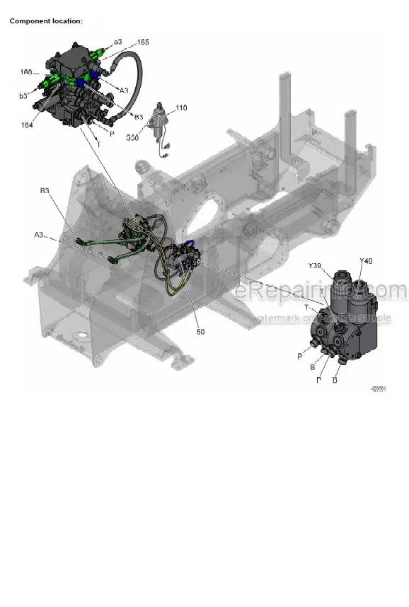
Hydraulic Diagrams
-HYDRAULIC COMPONENTS
Hydraulic Pump: Removal, Installation Start-Up
Double Variable-Displacement Pump DPVP 108
Hydraulic Motors Schedule
FMF Hydraulic Fixed Displacement Motor
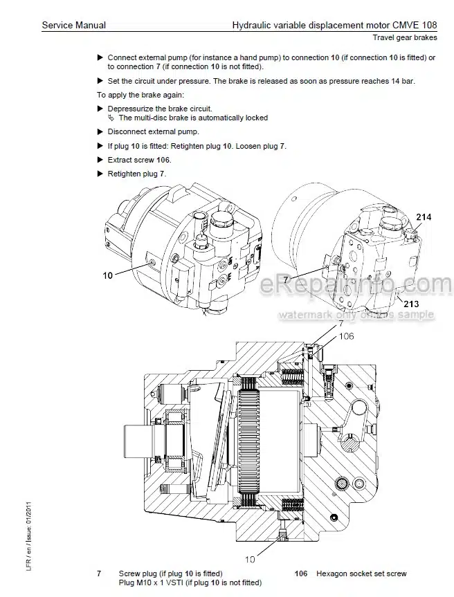
Hydraulic Variable Displacement Motor CMVE 108
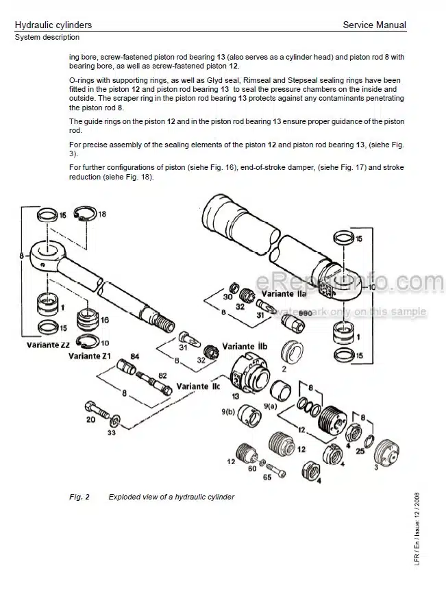
Hydraulic Cylinders
Presentation Of The Cylinders Of The Attachments
List Of The Hydraulic Cylinders (R 906 Advanced)
List Of The Hydraulic Cylinders (R 916 Advanced)
4-Way Servo Control (Working Functions)
Hydraulic Pilot Control Device With 2 Pedals And Damping System
6-Way Rotary Connection
Shockless Pressure Relief Valve
-ELECTRICAL SYSTEM
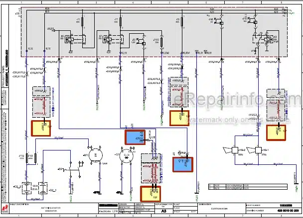
Components List Of The Electrical Diagrams
Electrical Diagrams Table
Electrical Diagrams
-SWING GEAR
Swing Gear «SAT»
Swing Brake / Positioning Brake
-SWING RING
Swing Ring
-TRAVEL GEAR
Gear Types Schedule
Technical Data Of The Travel Gears
Travel Gear FAT Of Construction Line P(C)
Removing And Reinstalling The Travel Gears FAT
Installation And Dismantling Of The Travel Gear Motor
-TRACK COMPONENTS
Track Components Of Crawler Excavators
List Of The Track Components On R 906 Advanced
List Of The Track Components On R 916 Advanced
List Of The Track Components On R 926 Advanced
Wear On The Track Components
Wear Limits
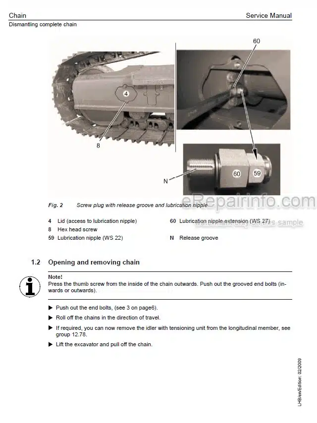
Removal, Installation Of Track Components
Spring Tension Units – Technical Data
Tension Unit And Guide Wheel Unit
Track Roller
Carrier Roller (Supported On One Side)
Slipring Seals
-OPTIONS
Schematics Chart For The Options
Hydraulic Schematics For Options
Electric Schematics For Options
-CAB / HEATER / AIR CONDITIONING SYSTEM
Air-Conditioning System
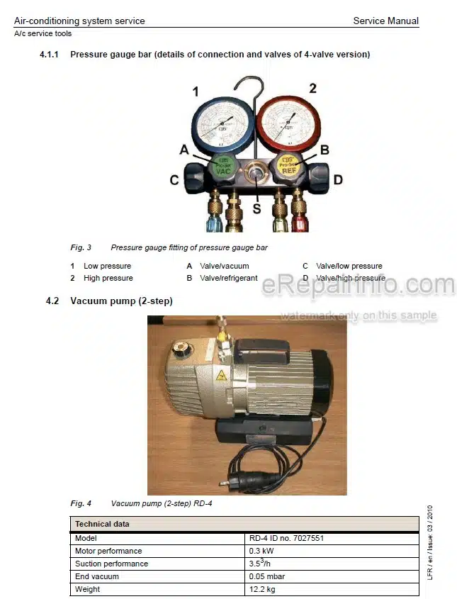
Air-Conditioning System Service
What you get
You will receive PDF file with high-quality manual on your email immediately after the payment.
Reviews
There are no reviews yet