Factory Repair Manual For Manitou Telehandler. Manual Contains Illustrations, Instructions, Diagrams For Step By Step Remove And Install, Assembly And Disassembly, Service, Inspection, Repair, Troubleshooting, Tune-Ups.
Format: PDF
Language: English
Pages: 430
Number: 647872EN (june 2021)
Bookmarks
Searchable
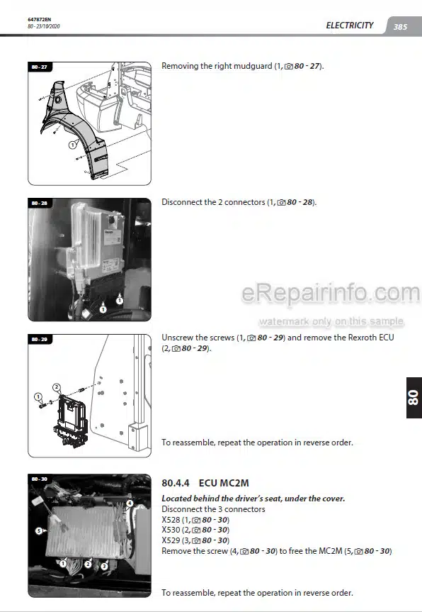
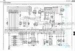
Wiring Diagrams
Hydraulic Diagrams
Model
Manitou Telehandler
MLA-T533 145 V PLUS D ST5 S1
Contents
-GENERAL CHARACTERISTICS AND SAFETY
General Instructions And Safety Notice
General Characteristics And Specification
General Location
General Control And Adjustment
-ENGINE
Engine Characteristics And Specification
Engine Schematic Diagram
Engine Components Location
Checking And Adjusting The Engine
Removing The Engine
General Information
Removing DEF (Diesel Exhaust Fluid) Circuit
Removing The Radiator
Engine Radiator
Specific Engine Tooling
-TRANSMISSION
Transmission Layouts
Position Of The Transmission Components
Transmission Assembly Tightening Torques
Pressure Take-Off Points
Pressure Test Ports
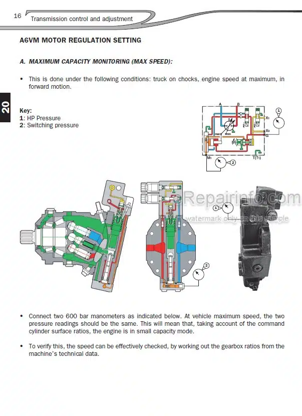
Pump / Motor Control And Adjustment
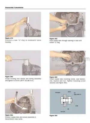
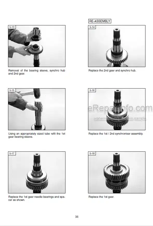
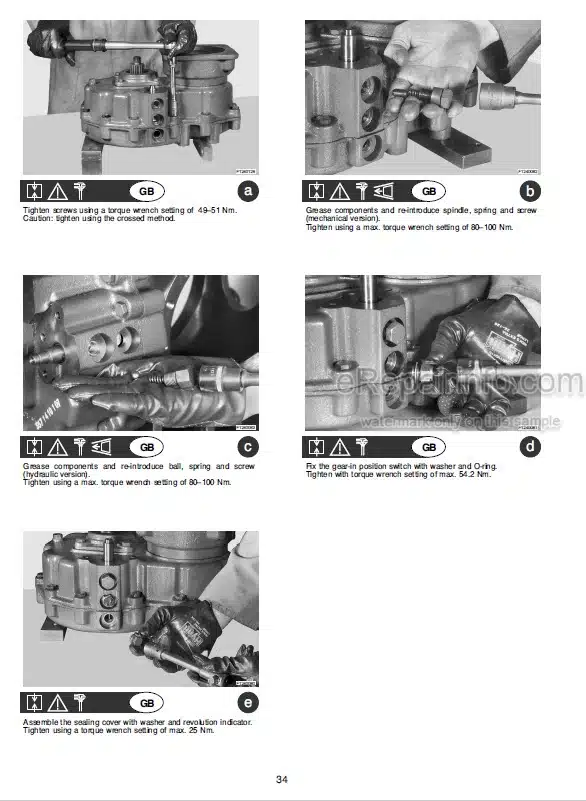
Removing The Hydrostatic Transmission
Special Tools For The Transmission
-AXLE
Removing The Axle
-BRAKE
Position Of The Brakes Components
Features And Technical Specifications Of The Brakes
Brakes System Layout
Brake Hydraulic Circuit
Removing The Brake Pump
-BOOM
Boom Characteristics And Specifications
Boom Components Location
Boom Control And Adjustment
Boom Removal
-HYDRAULIC
Hydraulic Schematic Diagram
Hydraulic Components Location
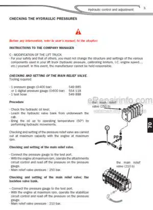
Hydraulic Control And Adjustment
Hydraulic Components Removal
-ELECTRICITY
Electrical Characteristics
Wiring Diagrams
Position Of The Electrical Components
Electrical Removal – Refit
Electrical Troubleshooting
Special Tools For The Electrical System
-DRIVER’S CAB
Driver’S Cab Removal
-FRAME-BODY
Pivot Articulation Removal
-OPTIONS – ATTACHMENTS
Air Conditioning Characteristics And Specifications
Air Conditioning Location
Air Conditioning Controls And Adjustments
Air Conditioning Troubleshooting
Specific Air Conditioning Tooling
What you get
You will receive PDF file with high-quality manual on your email immediately after the payment.



Reviews
There are no reviews yet