Factory Repair Manual For Manitou Telehandler. Manual Contains Illustrations, Instructions, Diagrams For Step By Step Remove And Install, Assembly And Disassembly, Service, Inspection, Repair, Troubleshooting, Tune-Ups.
Format: PDF
Language: English
Pages: 356
Number: 53112748
Searchable
Wiring Diagrams
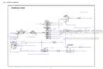
Hydraulic Diagrams
Model
Manitou Telehandler
MXT 840 – KOEL BSIV
Contents
-GENERAL CHARACTERISTICS AND SAFETY
General Instructions And Safety Notice
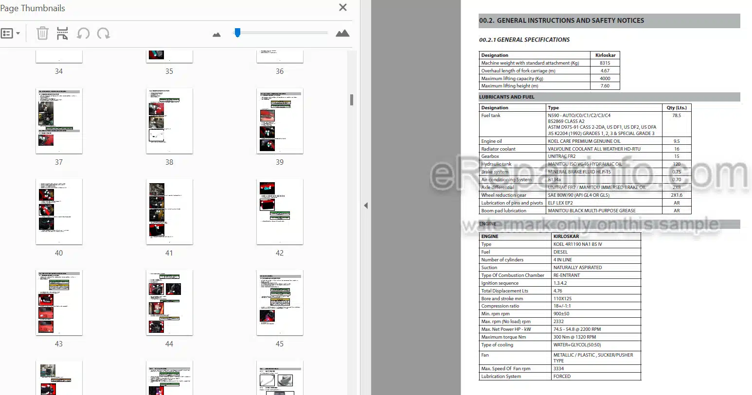
General Characteristics And Specifications
General Location
Maintenance
Options-Characteristics
General Control And Adjustment
-ENGINE
Engine Components Location
Tightening Torques
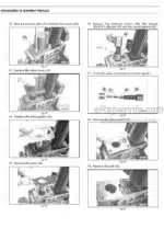
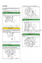
Air Intake System – Removal And Installation
Starter Motor – Removal And Installation
Attachment Belt – Removal And Installation
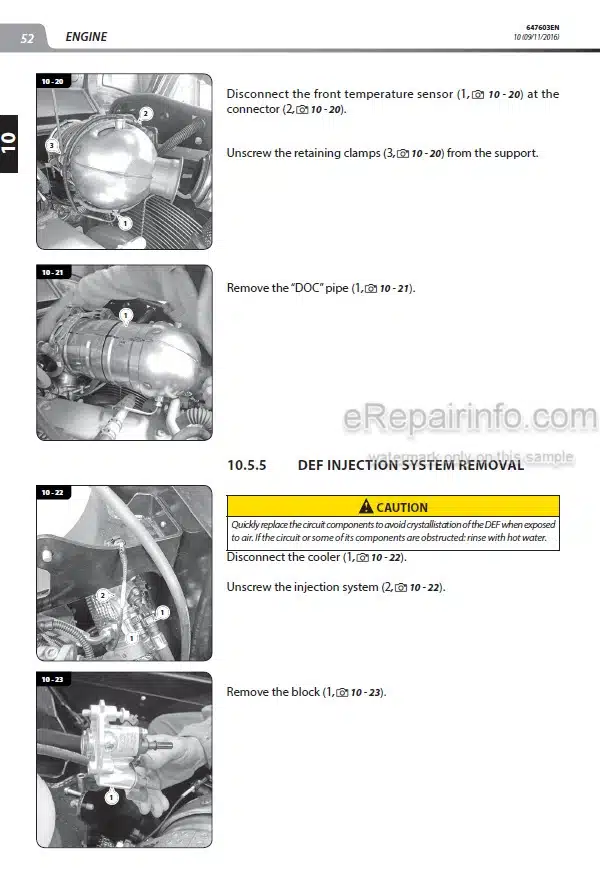
Exhaust System – Removal And Installation
Fuel Circuit – Removal And Installation
Cooling System – Removal And Installation
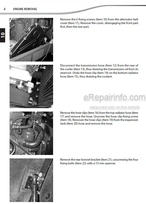
Engine-Removal
Engine – Installation
Specific Engine Tooling
-TRANSMISSION
Transmission Assembly
Transmission Removal And Installation
Transmission Tightening Torques
Gear Box And Converter
Gear Box – Oil Filters
Gear Box-Housing
Gear Box – Input & PTO Shafts
Gear Box – Reverse & Primary Shafts
Gear Box – Secondary Shaft
Gear Box – 4Wd Shaft
Gear Box – Speed Control
Gear Box – Control Valve
Transmission Hydraulic Circuit
Transmission Maintenance
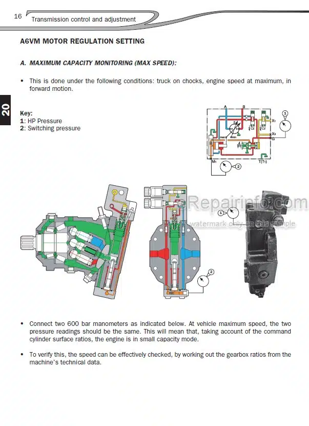
Pressure Checking
Special Tools
Disassembly & Assembly Operations-General Information
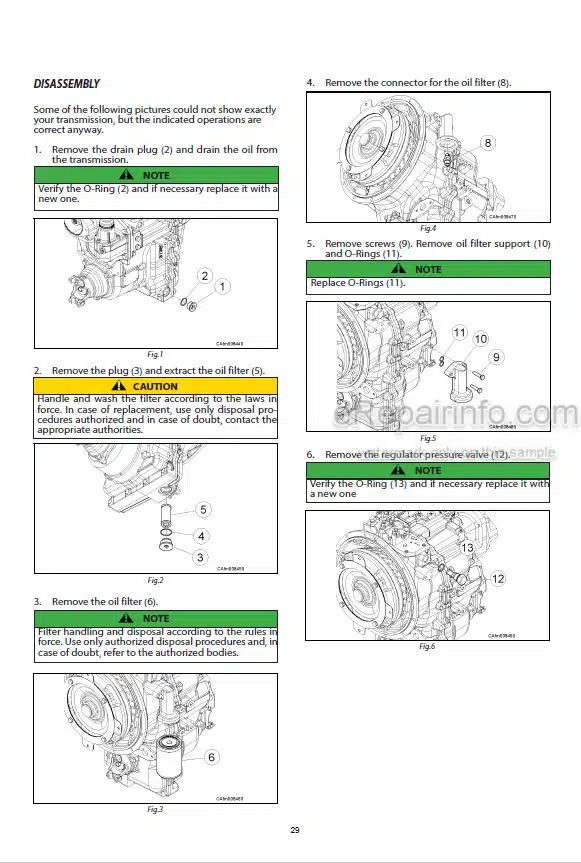
Disassembly & Assembly Operations-Plugs & Filters
Disassembly & Assembly Operations-Converter & Oil Pump
Disassembly & Assembly Operations-Pipes
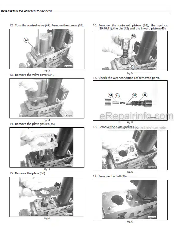
Disassembly & Assembly Operations-Hydraulic Control Valve
Disassembly & Assembly Operations-Transmission Housing
Disassembly & Assembly Operations-Shafts
Disassembly & Assembly Operations-Speed Controls
Disassembly & Assembly Operations-Troubleshooting
-AXLE
Specifications.
Safety Precautions
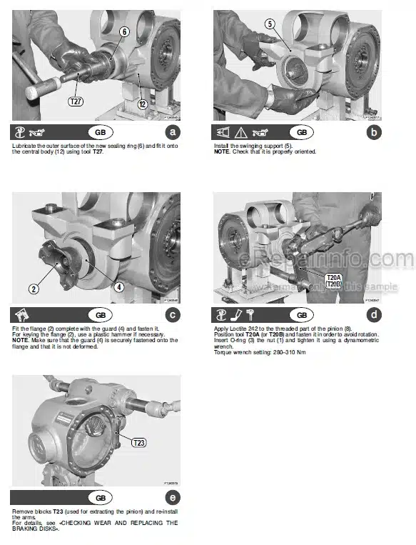
Checking Wear And Replacing The Braking Discs.
Complete Steering Case
Double U-Joint
Planetary Reduction Gear
Steering Cylinder
Differential Unit
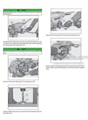
Bevel Pinion
Mechanical Parking Brake
Normal Differential Unit
Limited Slip Differential Unit (25% And 45%)
-BRAKE
Brakes – Service Brake And Parking Brake
Brake Assembly Component Location
Service Brake – Removal And Installation
Brake Bleeding Procedure
Brake Adjustment Procedure
Parking Brake – Removal And Installation
-BOOM
Boom Characteristics And Specifications
Shim Installation And Greasing Area Recommendations
Boom Removal And Installation
Tilting Cylinder Removal And Installation
Telescopic Cylinder Removal And Installation
-HYDRAULIC
Hydraulics-General Instructions
Hydraulic Components Location
Gear Pump-Removal And Installation
Lift Cylinder Removal And Installation
Cylinder Assembly And Disassembly
Cylinder Drawings
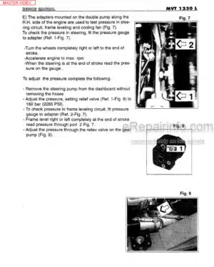
Pressure Testing
Hydraulic Schematic Diagram
-ELECTRICITY
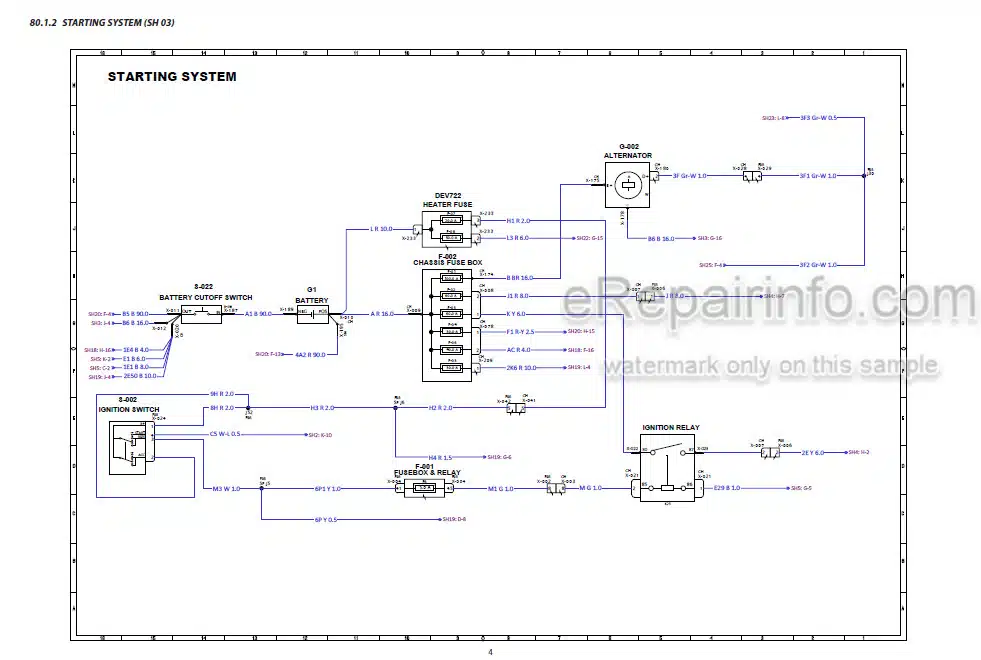
Electrical Schematic
Fuses And Relays In The Cab
Fuses And Relays Under The Engine Hood
Harnesses
-DRIVER’S CAB
Component Location
Driver’s Cab – Removal And Installation
Windshield Grill Removal And Installation
Driver’s Seat Removal And Installation
Cab Interior Trim Removal And Installation
Dashboard Switch Removal And Installation
Driver’s Cab Door Removal And Installation
-FRAME – BODY
Tank Cover Removal And Installation
-OPTIONS – ATTACHMENTS
Air Conditioning Option – Characteristics And Specifications
Air Conditioning Location
Air Conditioning Controls & Adjustments
Air Conditioning Belts – Removal
Air Conditioning Trouble Shooting
What you get
You will receive PDF file with high-quality manual on your email immediately after the payment.

Reviews
There are no reviews yet