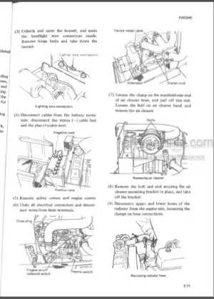
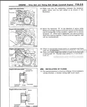
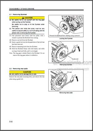
Factory Service Manual For Mitsubishi Diesel Engine For Forklift. Manual Contains Illustrations, Instructions, Diagrams For Step By Step Remove And Install, Assembly And Disassembly, Service, Inspection, Repair, Troubleshooting, Tune-Ups.
Format: PDF
Language: English
Pages: 742
Number: SMEEA-AF12C-200
Bookmarks: Yes
Searchable: Yes
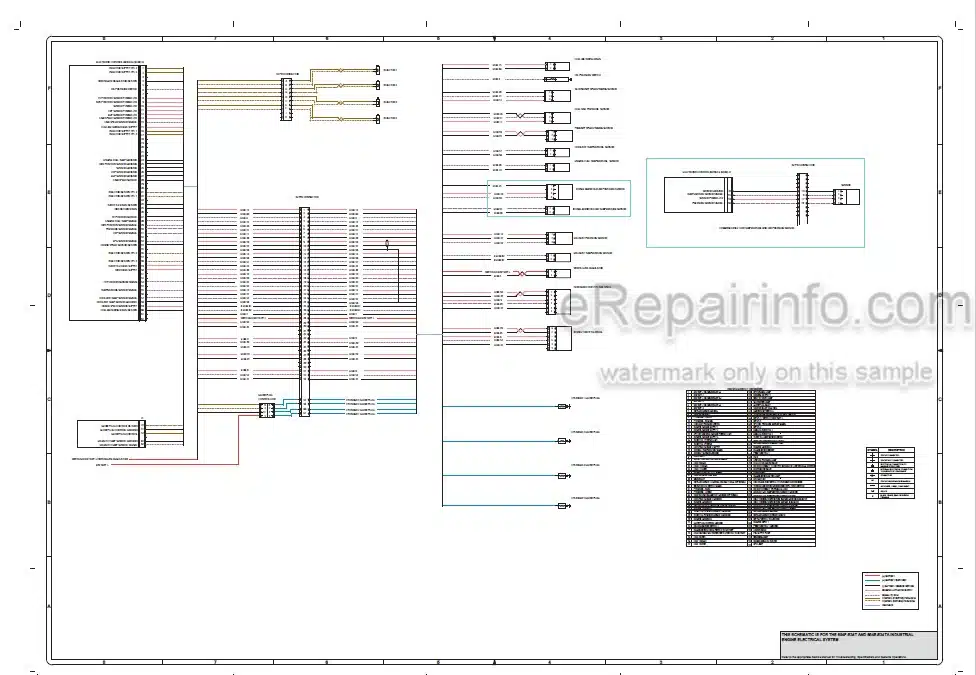
Wiring Diagrams: Yes
Model
Mitsubishi Diesel Engine For Forklift
854E
854F
For Use With FD70N Chassis Service Manuals And FD40N1 To FD55N1 And FD40NB To FD55NB Chassis Service Manuals
Contents
-SPECIFICATION
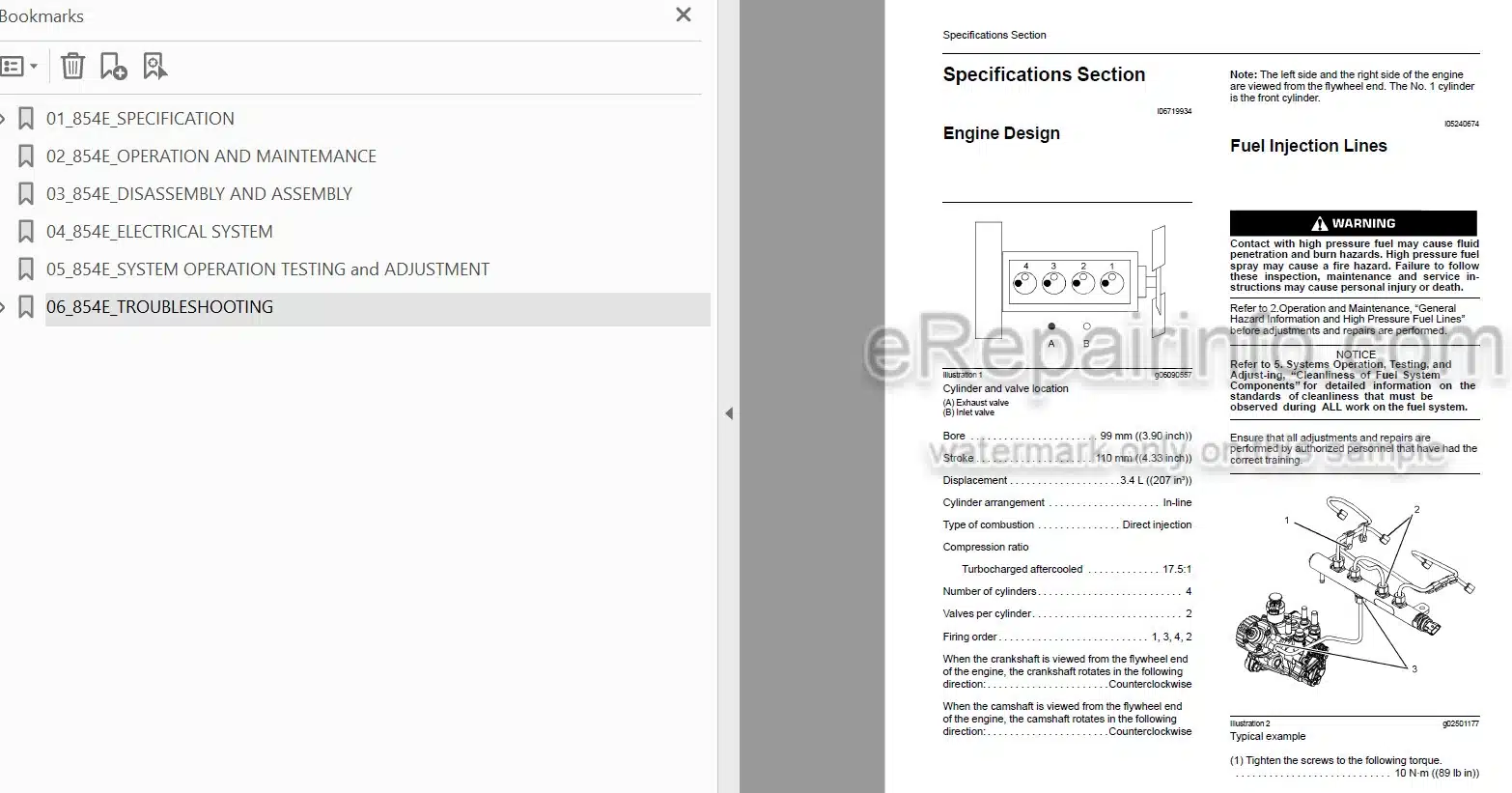
Engine Design
Fuel Injection Lines
Fuel Injection Pump
Fuel Injectors
Fuel Filter Base (Secondary Fuel Filter Base)
Fuel Filter Base (Primary Fuel Filter Base)
Fuel Manifold (Rail)
Lifter Group
Rocker Shaft
Valve Mechanism Cover
Cylinder Head Valves
Cylinder Head
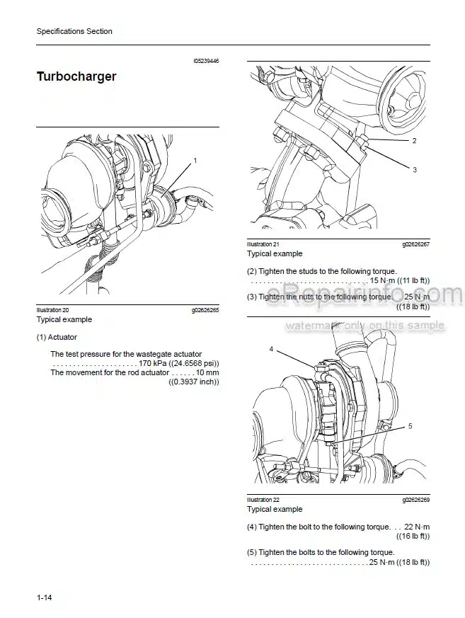
Turbocharger
Exhaust Gas Valve (NRS)
Exhaust Cooler (NRS)
Exhaust Manifold
Flexible Exhaust Pipe
Diesel Particulate Filter (Wall Flow Diesel Particulate Filter (DPF))
Diesel Particulate Filter (Through Flow Diesel Particulate Filter (DPF))
Camshaft
Camshaft Bearings
Engine Oil Filter Base
Engine Oil Cooler
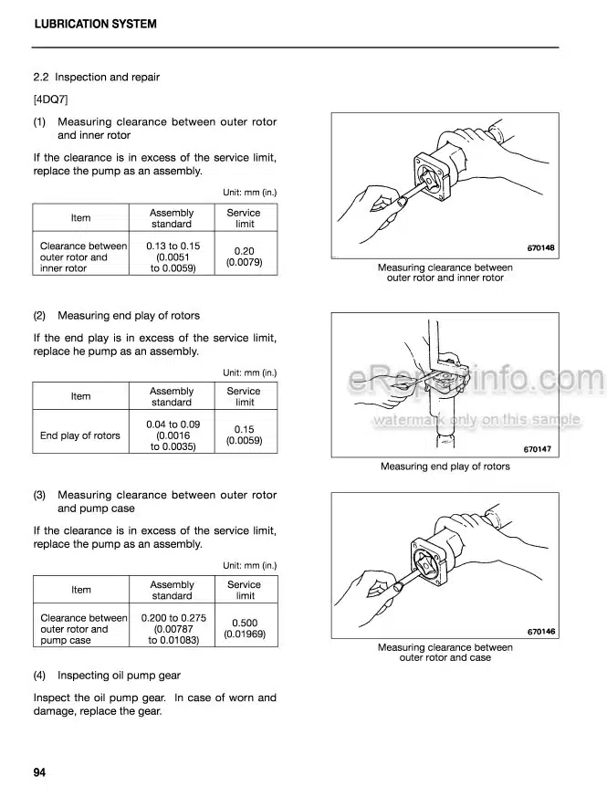
Engine Oil Pump
Engine Oil Pressure
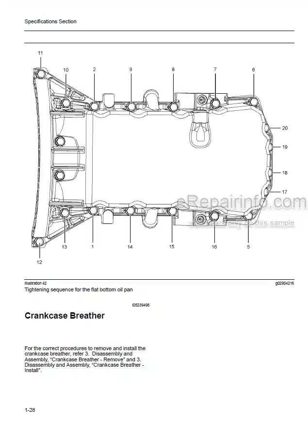
Engine Oil Pan (Pressed Steel Oil Pan)
Engine Oil Pan (Aluminum Oil Pan)
Engine Oil Pan (Cast Iron Oil Pan)
Crankcase Breather
Water Temperature Regulator and Housing
Water Pump
Cylinder Block
Crankshaft
Connecting Rod Bearing Journal
Main Bearing Journal
Connecting Rod
Piston and Rings
Piston Cooling Jet
Balancer
Front Housing and Covers
Gear Group (Front)
Flywheel
Flywheel Housing
Crankshaft Pulley
Fan Drive
Engine Lifting Bracket
Alternator
Starter Motor
Coolant Temperature Sensor
Boost Pressure Sensor (If equipped)
Oxygen Sensor
Inlet Manifold Temperature Sensor (If equipped)
Inlet Manifold Temperature and Pressure Sensor (If equipped)
Temperature Sensor (DPF Inlet)
Temperature Sensor (DOC Inlet)
Pressure Sensor (NOx Reduction System)
Temperature Sensor (NOx Reduction System)
Speed/Timing Sensor
Electronic Control Module
Glow Plugs
-OPERATION AND MAINTENANCE
Safety
Operation
Maintenance
Warranty
Reference Information
-DISASSEMBLY AND ASSEMBLY
Inspection of Parts
Fuel Priming Pump – Remove and Install
Flow Control Valve – Remove and Install
Fuel Filter Base – Remove and Install
Water Separator and Fuel Filter (Primary) – Remove and Install
Fuel Manifold (Rail) – Remove and Install
Fuel Injection Lines – Remove
Fuel Injection Lines – Install
Exhaust Cooler (NRS) – Remove and Install
Throttle Valve (Intake Air) – Remove and Install (Rear Facing Inlet Elbow)
Throttle Valve (Intake Air) – Remove and Install (Side Facing Inlet Elbow)
Fuel Injection Pump – Remove
Fuel Injection Pump – Install
Fuel Injection Pump Gear – Remove
Fuel Injection Pump Gear – Install
Electronic Unit Injector – Remove
Electronic Unit Injector – Install
Turbocharger – Remove (Top Mounted Turbochargers)
Turbocharger – Remove (Side Mounted Turbochargers)
Turbocharger – Install (Top Mounted Turbochargers)
Turbocharger – Install (Side Mounted Turbochargers)
Wastegate Solenoid – Remove and Install
Exhaust Gas Recirculation Valve – Remove and Install
Flexible Exhaust Pipe – Remove and Install
Exhaust Manifold – Remove and Install
Diesel Particulate Filter – Remove (Through Flow Diesel Particulate Filter)
Diesel Particulate Filter – Remove (Wall Flow Diesel Particulate Filter)
Diesel Particulate Filter – Install (Through Flow Diesel Particulate Filter)
Diesel Particulate Filter – Install (Wall Flow Diesel Particulate Filter )
Support and Mounting (CEM) – Remove and Install (Option 3)
Support and Mounting (CEM) – Remove and Install (Option 2)
Support and Mounting (CEM) – Remove and Install (Option 1)
Inlet Manifold – Remove and Install
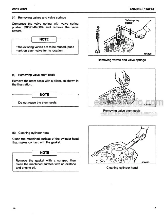
Inlet and Exhaust Valve Springs – Remove and Install
Inlet and Exhaust Valves – Remove and Install
Inlet and Exhaust Valve Guides – Remove and Install
Engine Oil Filter Base – Remove and Install
Engine Oil Cooler – Remove
Engine Oil Cooler – Install
Engine Oil Relief Valve – Remove and Install
Engine Oil Pump – Remove
Engine Oil Pump – Install
Water Pump – Remove
Water Pump – Install
Water Temperature Regulator – Remove and Install
Engine Lifting Bracket – Remove
Engine Lifting Bracket – Install
Flywheel – Remove 1
Flywheel – Install
Crankshaft Rear Seal – Remove and Install
Flywheel Housing – Remove and Install (Stressed Cylinder Block)
Flywheel Housing – Remove and Install (Non- Stressed Cylinder Block)
Power Take-Off Drive – Remove and Install
Crankshaft Pulley – Remove and Install
Crankshaft Front Seal – Remove and Install
Front Cover – Remove and Install
Idler Gear – Remove
Idler Gear – Install
Housing (Front) – Remove
Housing (Front) – Install
Accessory Drive – Remove and Install
Crankcase Breather – Remove
Crankcase Breather – Install
Valve Mechanism Cover – Remove and Install
Rocker Shaft and Pushrod – Remove
Rocker Shaft – Disassemble
Rocker Shaft – Assemble
Rocker Shaft and Pushrod – Install
Cylinder Head – Remove
Cylinder Head – Install
Lifter Group – Remove and Install
Camshaft – Remove and Install
Camshaft Gear – Remove and Install
Camshaft Bearings – Remove and Install
Engine Oil Pan – Remove and Install (Pressed Steel Oil Pan)
Engine Oil Pan – Remove and Install (Cast Iron Engine Oil Pan)
Balancer – Remove
Balancer – Install
Piston Cooling Jets – Remove and Install
Pistons and Connecting Rods – Remove
Pistons and Connecting Rods – Disassemble
Pistons and Connecting Rods – Assemble
Pistons and Connecting Rods – Install
Connecting Rod Bearings – Remove (Connecting rods in position)
Connecting Rod Bearings – Install (Connecting rods in position)
Crankshaft Main Bearings – Remove and Install
Crankshaft – Remove
Crankshaft – Install
Crankshaft Timing Ring – Remove and Install
Bearing Clearance – Check
Camshaft Position Sensor – Remove and Install
Crankshaft Position Sensor – Remove and Install
Coolant Temperature Sensor – Remove and Install
Engine Oil Pressure Switch – Remove and Install
Fuel Temperature Sensor – Remove and Install
Oxygen Sensor – Remove and Install (Catalytic Converter)
Temperature Sensor (Exhaust) – Remove and Install
Temperature Sensor (DPF) – Remove and Install
Pressure Sensor (DPF) – Remove and Install
Pressure Sensor (Exhaust Back Pressure) – Remove and Install
Inlet Manifold Temperature Sensor – Remove and Install
Inlet Manifold Pressure Sensor – Remove and Install
Glow Plugs – Remove and Install
Alternator Belt – Remove and Install
Idler Pulley – Remove and Install
Fan – Remove and Install
Fan Drive – Remove and Install
Alternator – Remove
Alternator – Install
Electric Starting Motor – Remove and Install
ELECTRICAL SYSTEM
-SYSTEM OPERATION TESTING AND ADJUSTING
General Information
Engine Operation
Testing and Adjusting-Fuel System
Testing and Adjusting-Air Inlet and Exhaust System
Testing and Adjusting-Lubrication System
Testing and Adjusting-Cooling System
Testing and Adjusting-Basic Engine
Testing and Adjusting-Electrical System
-TROUBLESHOOTING
Introduction
Electronic System Overview
Configuration Parameters
Symptom Troubleshooting
Circuit Tests
Service
What you get
You will receive PDF file with high-quality manual on your email immediately after the payment.
Reviews
There are no reviews yet