Repair Manual For New Holland CX700 CX800 series Combines. Illustrations, instructions, diagrams for step by step remove and install, assembly and disassembly, service, inspection, repair, troubleshooting, tune-up.
Format: PDF
Language: English
Pages: 3810
Bookmarks: Yes
Searchable: Yes
Number: 87360012
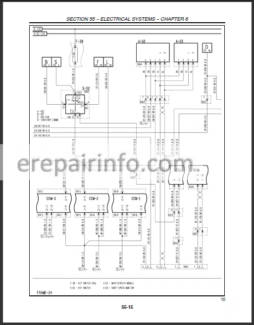
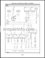
Wiring Diagrams: Yes
Hydraulic Diagrams: Yes
Model
New Holland
CX720
CX740
CX760
CX780
CX820
CX840
CX860
CX880
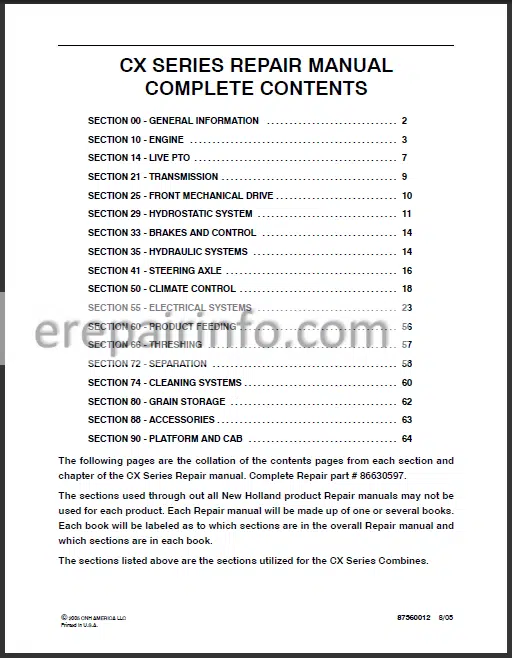
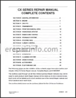
Contents
- – General Information
Important Information
General Instructions
Shimming
Rotating Shaft Seals
O Ring Seals
Sealing Compounds
Cotter Pins
Spare Parts
Tools
Safety Regulations
Accident Prevention
Safety Rules
General Guidelines
Start Up
Hydraulic Systems
Wheels And Tyres
Removal And ReFitting
Explanation Of Machine Serial Numbers
Units Of Measure Conversion Chart
Minimum Hardware Tightening Torques
Drives
Main Output Shaft
Unloading Output Shaft - – Engine
Greases And Sealants
Fault Finding
Description And Operation
Engine OverhaulIntroduction
Injection Pump Timing Check
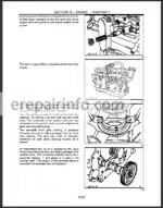
Engine Disassembly And Overhaul:
Cylinder Head, Valves And Related Parts
Front Cover And Timing Gears
Oil Pan
Flywheel
Rear Cover Plate
Oil Pump
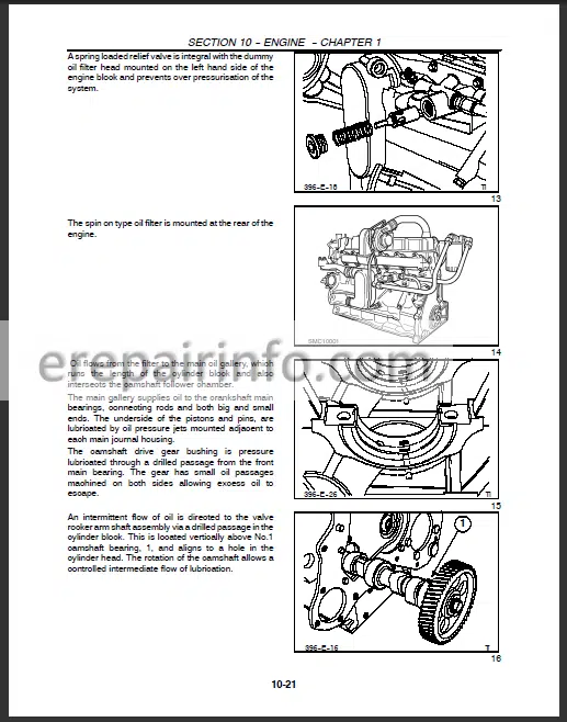
Oil Pressure Relief Valve
Camshaft, Tappets And Camshaft Bearings
Pistons And Cylinder Block
Crankshaft
Engine Compression Test - – Live Pto
- – Transmission
Shifting Diagram
Traction Gearbox
Cover Removal, Disassembly And Assembly
Differential Shafts And DifferentialRemoval
Differential Shaft
Selector Shaft
Drive Shaft
Input Shaft
Shifting Disc And Shifting Drive Gear
Differential
Drive Shaft
Input Shaft
Traction Gearbox
Shifting Disc And Shifting Drive Gear
Input Shaft
Drive Shaft
Selector Shaft
Differential Half Shafts And Differential
Cover - – Front Mechanical Drive
Gearbox Shafts
Wheel Bolt
Planetary Final Drive
Planetary Final Drive
Planet Gear Carrier
Sun Gears
Output Shaft
Input Shaft - – Hydrostatic System
Hydrostatic Drive Schematic
Explanation Of Hydraulic Symbols - – Brakes And Control
Brake Linings
Brake Cylinders
Bleeding The Brakes
Bleeding The LeftHand Side Circuit
Bleeding The Connection Pipe Between The Two Main Cylinders
Bleeding The RightHand Side Circuit
Brake Shoe And Brake Disc
Parking Brake Shoe And Parking Brake Disc
Parking Brake
Parking Brake Piston Travel And Adjustment
Parking Brake Linings
Bleeding The Hydraulic Parking Brake Cylinder
Parking Brake Cylinder - – Hydraulic Systems
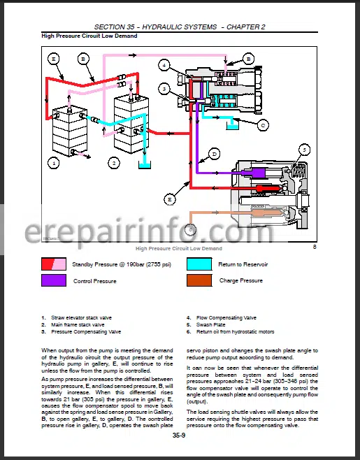
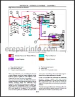
High Pressure Circuit Diagram
High Pressure System Component Locations
High Pressure System Component Descriptions
Low Pressure Circuit Diagram
Low Pressure System Component Locations
Low Pressure System Component Descriptions
– Steering Axle
Heavy Duty Adjustable Steering Axle (Hdasa)
Powered Rear Axle (Pra)
Steering Axle Adjustment
Powered Rear Axle Adjustment
Height Position
Track Width Position - – Climate Control
A/C Cycle
Refrigerant
Testing And Troubleshooting, General
Pressure / Temperature Relationships ,
Preliminary Troubleshooting And Testing
Preliminary Diagnosis Chart
Test ProcedureStabilizing The System
A/C System Performance Test And Diagnosis Chart
Gauge Readings And Interpretations - – Product Feeding
Upper Shaft
Slip Clutch
Bottom Shaft
Intermediate Roll
Header Drive Shaft
Reversing System
Cradle
Front Face Adjustment
Intermediate Plate - – Threshing
Configuration Of Functional Parts
OpDrum Drive Belt
OpRightHand Side Drum Bearing
OpLeftHand Side Drum Bearing
OpDrum
OpDrum Rasp Bar Replacement (Standard Or Universal Drum)
OpDrum Bar Replacement (Universal Drum)
Types Of Drum Concaves
Concave Specifications
OpDrum Concave
Setting Of Different Types Of Concaves
OpPivot Plate Adjustment - – Separation
LeftHand Side Beater Bearing
RightHand Side Beater Bearing
Beater Shaft - – Cleaning Systems
Upper Cleaning Shoe
Grain Pan
Lower Cleaning Shoe
Cleaning Shoe Support Arm Bushings
Connecting Arm Pivot Bushings
Drive And Upper Connecting Arm Bushing
Lower Connecting Arm Bushings
Cleaning Shoe Seals
Leveling Frame - – Grain Storage
Grain Elevator
Grain Elevator Chain
Grain Elevator Upper Shaft
Grain Elevator Upper Shaft Adjustment
Grain Flow Sensor Plate Adjustment
Sensitivity Of The Moisture Sensor
Sensitivity Set
Bubble Up Gearbox - – Accessories
Belts Chopper Rear Drive Belt
Belts Chopper Front Drive Belt
Chopper Knives
Windrow Shield
Deflector Plate
Chopper Body
Rotor Assembly
Rotor
Chop / Drop Baffle
Intermediate Drive Sheave - – Platform And Cab
Air Ride Seat
Compressor / Bellows
Shock Absorber
Adjuster
Windshield Wiper Motor
Steering Column
Outside Cab Roof Lights
What you get
You will receive PDF file with high-quality manual on your email immediately after the payment.


Reviews
There are no reviews yet