Repair Manual For New Holland E27 Hydraulic Excavator. Illustrations, instructions, diagrams for step by step remove and install, assembly and disassembly, service, inspection, repair, troubleshooting, tune-up.
Format: PDF
Language: English
Pages: 742
Bookmarks: Yes
Searchable: Yes
Number: 87360159NA
Wiring Diagrams: Yes
Hydraulic Diagrams: Yes
Model
New Holland E27
Contents
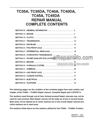
- – General
Engine Nomenclature
Specifications
Fuel Oil, Lubricating Oil And Cooling Water
Fuel Oil
Lubricating Oil
Cooling Water
Engine External Views
Structural Description
Exhaust Gas Emission Regulation
The Emission Standard In Usa
Engine Identification
Guarantee Conditions For The Epa Emission Standard - – Inspection And Adjustment
Periodic Maintenance Schedule
Periodic Inspection And Maintenance Procedure
Check Before Daily Operation
Adjusting The NoLoad Maximum Or Minimum Speed
Sensor Inspection
Oil Pressure Switch
Thermo Switch
Water Leak Check In Cooling Water System
Radiator Cap Inspection
Thermostat Inspection
Adjusting Operation
Long Storage - – Troubleshooting
Preparation Before Troubleshooting
Quick Reference Table For Troubleshooting
Troubleshooting By Measuring Compression Pressure - – Disassembly, Inspection And Reassembly Of Engines
Complete Disassembly And Reassembly
Introduction
Special Service Tools
Complete Disassembly
Precautions Before And During Reassembly
Adjusting Operation
Cylinder Head
Components
Servicing Points
Parts Inspection And Measurement
Valve Seat Correction
Valve Guide Replacement
Valve Stem Seal Replacement
Gear Train And Camshaft
Components
Disassembly Procedure:
Reassembly Procedure:
Servicing Points
Parts Inspection And Measurement
Oil Seal Replacement (Gear Case Side)
Camshaft Bushing Replacement
Cylinder Block
Components
Disassembly Procedure:
Reassembly Procedure:
Servicing Points
Parts Inspection And Measurement
Cylinder Bore Correction
Piston Pin Bushing Replacement
Oil Seal Replacement (Flywheel Housing Side) - – Lubrication System
Lubrication System Diagram
Trochoid Pump Components
Disassembly(Reverse The Procedure Below For Assembly)
Servicing Points
Parts Inspection And Measurement
Trochoid Pump Inspection And Measurement - – Cooling System
Cooling Water System
Cooling Water Pump Components
Disassembly (Reverse The Procedure Below For Assembly)
Servicing Points - – Fuel Injection Pump/Governor
Introduction
Fuel Injection Pump
Fuel System Diagram
External View And Components
Disassembly Procedure:
Assembly Procedure
Servicing Points - – Turbocharger: Disassembly, Inspection And Reassembly
Structure And Functions
Main Specifications
Construction
Structural And Functional Outline
Components
Service Standards And Tightening Torque
Service Standards
Tightening Torque
Periodic Inspection Procedure
Periodic Inspection Intervals
Inspection Procedure
Waste Gate Valve Adjustment Procedure
Disassembly Procedure
Preparation For Disassembly
Inspection Before Disassembly
Washing And Inspection Procedure
Washing
Inspection Procedure
Reassembly Procedure
Preparation For Reassembly
Reassembly
Handling After Disassembly And Reassembly
Instructions For Turbocharger Installation
Troubleshooting
Excessively Exhaust Smoke
White Smoke Generation
Sudden Oil Decrease
Decrease In Output
Poor (Slow) Response (Starting) Of Turbocharger
Abnormal Sound Or Vibration - – Starting Motor
- – Alternator
Wiring Diagram
Standard Output Characteristics
Inspection
Troubleshooting - – Electric Wiring
Electric Wiring Diagram
Precaution On Electric Wiring
Current Limiter
Section Area And Resistance Of Electric Wire - – Service Standards
Engine Tuning
Engine Body
Cylinder Head
Gear Train And Camshaft
Cylinder Block
Lubricating Oil System (Trochoid Pump)
Outside Clearance Of Outer Rotor
Side Clearance Of Outer Rotor
Inside Clearance Of Inner Rotor
Rotor Shaft Clearance - – Tightening Torque For Bolts And Nuts
Tightening Torques For Main Bolts And Nuts
Tightening Torques For Standard Bolts And Nuts
What you get
You will receive PDF file with high-quality manual on your email immediately after the payment.


Reviews
There are no reviews yet